Dewalt DCG412B Instruction Manual - Page 15
Accessories, Mounting Guard - grinder
 |
View all Dewalt DCG412B manuals
Add to My Manuals
Save this manual to your list of manuals |
Page 15 highlights
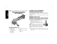
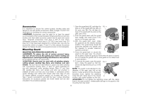
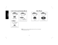
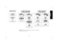
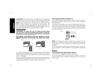
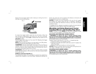
English Accessories It is important to choose the correct guards, backing pads and flanges to use with grinder accessories. Refer to pages 14 and 15 for information on choosing the correct accessories. WARNING: Accessories must be rated for at least the speed recommended on the tool warning label. Wheels and other accessories running over their rated accessory speed may fly apart and cause injury. Threaded accessories must have a 5/8"-11 hub. Every unthreaded accessory must have a 7/8" (22.2 mm) arbor hole. If it does not, it may have been designed for a circular saw. Use only the accessories shown on pages 14 and 15 of this manual. Accessory ratings must always be above tool speed as shown on tool nameplate. Mounting Guard MOUNTING AND REMOVING GUARD (FIG. 4) WARNING: To reduce the risk of serious personal injury, turn tool off and remove the battery pack before making any adjustments or removing/installing attachments or accessories. An accidental start-up can cause injury. CAUTION: Guards must be used with all grinding wheels, cutting wheels, sanding flap discs, wire brushes, and wire wheels. The tool may be used without a guard only when sanding with conventional sanding discs. A Type 27 guard (intended for use with depressed center grinding wheels [Type 27 and Type 29], sanding flap discs, wire wheels and wire cup brushes) is available at extra cost from your local dealer or authorized service center. Grinding and cutting with wheels other than Type 27 and 29 require different accessory guards not included with tool. A Type 1 guard is provided for use with the Type 1 wheel. Mounting instructions for accessory guards are shown below and are also included in the accessory package. 1. Open the guard latch (K), and align the FIG. 4 lugs (L) on the guard with the slots on L the gear case (M). This will align the lugs on the guard with the slots on the gear case cover. 2. Push the guard down until the guard lugs engage and rotate freely in the groove on the gear case hub. 3. With the guard latch open, rotate M K the guard (I) into the desired working position. The guard body should be positioned between the spindle and the operator to provide maximum operator protection. 4. Close the guard latch to secure the I guard on the gear case. You should not be able to rotate the guard by hand when the latch is closed. Do not operate the grinder with a loose guard or the clamp lever in open position. 5. To remove the guard, open the guard FIG. 5 latch, rotate the guard so that the arrows are aligned and pull up on the guard. NOTE: The guard is pre-adjusted to the diameter of the gear case hub at the factory. If, after a period of time, the guard becomes loose, tighten the adjusting screw (N) with clamp lever in the closed N position with guard installed on the tool. CAUTION: Do not tighten the adjusting screw with the clamp lever in the open position. Undetectable damage to the guard or the mounting hub may result. 13
-
 1
1 -
2
-
3
-
4
-
5
-
6
-
7
-
8
-
9
-
 10
10 -
 11
11 -
 12
12 -
 13
13 -
 14
14 -
 15
15 -
 16
16 -
 17
17 -
 18
18 -
 19
19 -
 20
20 -
21
-
22
-
23
-
24
-
25
-
26
-
27
-
28
-
29
-
30
-
31
-
32
-
33
-
34
-
35
-
36
-
37
-
38
-
39
-
40
-
41
-
42
-
43
-
44
-
45
-
46
-
47
-
48
-
49
-
50
-
51
-
52
-
53
-
54
-
55
-
56
-
57
-
58
-
59
-
60
-
61
-
62
-
63
-
64
-
65
-
66
-
67
-
68
-
69
-
70
-
71
-
72
-
73
-
74
-
75
-
76
-
77
-
78
-
79
-
80
-
81
-
82
-
83
-
84
-
85
-
86
-
87
-
88
 |
 |
