Dewalt DCS390L Instruction Manual - Page 13
Installing and Removing the Battery, Pack Fig. 2, 3, Switch Fig. 3, Changing Blades
 |
View all Dewalt DCS390L manuals
Add to My Manuals
Save this manual to your list of manuals |
Page 13 highlights
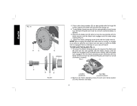
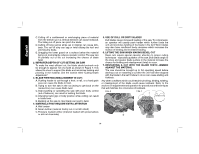
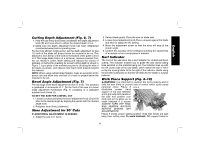
English FIG. 2 FIG. 3 A NOTE: This tool has no provision to lock the switch in the ON position, and should never be locked ON by any other means. B FIG. 4a L K N F M Installing and Removing the Battery Pack (Fig. 2, 3) NOTE: Make sure your battery pack is fully charged. WARNING: Make certain the switch lock-off button (A) is engaged to prevent switch actuation before removing or installing battery. To install the battery pack into the tool handle, align the base of the tool with the notch inside the tool's handle and slide the battery pack firmly into the handle until you hear the lock snap into place. To remove the battery pack from the tool, press the release buttons (M) and firmly pull the battery pack out of the tool handle. Insert it into the charger as described in the charger manual (Fig. 2). Switch (Fig. 3) Release switch lock-off button (A) by pressing button as shown (Fig. 3). Pull the trigger switch (B) to turn the motor ON. Releasing the trigger switch turns the motor OFF. Releasing the trigger switch also automatically actuates lock-off button. O G H Changing Blades TO INSTALL THE BLADE (FIG. 4, 5) 1. Place inner clamp washer (N) on saw spindle with the large flat surface facing out toward the blade (Fig. 4a, 4b). 2. Retract the lower blade guard (G) and place blade on saw spindle against the inner clamp washer, making sure that the blade will rotate in the proper direction (the direction of the rotation arrow on the saw blade and the teeth must point in the same direction as the direction of rotation arrow on the lower blade guard). Do not assume that the printing on the blade will always be facing you when properly installed. When retracting the lower blade guard to install the blade, check the condition and operation of the lower blade guard to assure that it is working properly. Make sure it moves freely and does not touch the blade or any other part, in all angles and depths of cut. 11
-
 1
1 -
2
-
3
-
4
-
5
-
6
-
7
-
 8
8 -
 9
9 -
 10
10 -
 11
11 -
 12
12 -
 13
13 -
 14
14 -
 15
15 -
 16
16 -
 17
17 -
 18
18 -
19
-
20
-
21
-
22
-
23
-
24
-
25
-
26
-
27
-
28
-
29
-
30
-
31
-
32
-
33
-
34
-
35
-
36
-
37
-
38
-
39
-
40
-
41
-
42
-
43
-
44
-
45
-
46
-
47
-
48
-
49
-
50
-
51
-
52
-
53
-
54
-
55
-
56
-
57
-
58
-
59
-
60
-
61
-
62
-
63
-
64
-
65
-
66
-
67
-
68
 |
 |
