Dewalt DCS390L Instruction Manual - Page 17
Cutting Depth Adjustment Fig. 6, 7, Bevel Angle Adjustment Fig. 7, Shoe Adjustment for 90˚ Cuts,
 |
View all Dewalt DCS390L manuals
Add to My Manuals
Save this manual to your list of manuals |
Page 17 highlights
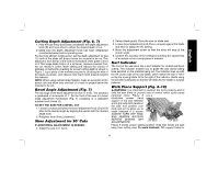
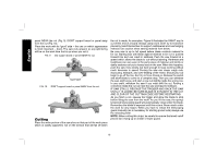
English Cutting Depth Adjustment (Fig. 6, 7) 1. Hold the saw firmly and loosen (clockwise) the depth adjustment knob (D) and move shoe to obtain the desired depth of cut. 2. Make sure the depth adjustment knob has been retightened (counterclockwise) before operating saw. For the most efficient cutting action, set the depth adjustment so that 1/2 tooth of the blade will project below the material to be cut. This distance is from the tip of the tooth to the bottom of the gullet in front of it. This keeps blade friction at a minimum, removes sawdust from the cut, results in cooler, faster sawing and reduces the chance of kickback. A method for checking for correct cutting depth is shown in Figure 7. Lay a piece of the material you plan to cut along the side of the blade, as shown, and observe how much tooth projects beyond the material. NOTE: When using carbide-tipped blades, make an exception to the above rule and allow only one-half of a tooth to project below the material to be cut. Bevel Angle Adjustment (Fig. 7) The full range of the bevel adjustment is from 0˚ to 50˚. The quadrant is graduated in increments of 1˚. On the front of the saw is a bevel angle adjustment mechanism (Fig. 7) consisting of a calibrated quadrant and a knob (J). TO SET THE SAW FOR A BEVEL CUT 1. Loosen (counterclockwise) the bevel adjustment knob (J) and tilt shoe to the desired angle by aligning the pointer with the desired angle mark. 2. Retighten knob firmly (clockwise). Shoe Adjustment for 90˚ Cuts IF ADDITIONAL ADJUSTMENT IS NEEDED: 1. Adjust the saw to 0˚ bevel. 2. Retract blade guard. Place the saw on blade side. 3. Loosen bevel adjustment knob. Place a square against the blade and shoe to adjust the 90˚ setting. 4. Move the adjustment screw so that the shoe will stop at the proper angle. 5. Confirm the accuracy of the setting by checking the squareness of an actual cut on a scrap piece of material. Kerf Indicator The front of the saw shoe has a kerf indicator for vertical and bevel cutting. This indicator enables you to guide the saw along cutting lines penciled on the material being cut. The indicator lines up with the left (outer) side of the saw blade, which makes the slot or "kerf" cut by the moving blade fall to the right of the indicator. Guide along the penciled cutting line so that the kerf falls into the waste or surplus material. Work Piece Support (Fig. 8-10) WARNING: It is important to support the work properly and to hold the saw firmly to prevent loss of control which could cause personal injury. Figure 8 FIG. 8 illustrates proper hand support of the saw. Maintain a firm grip with both hands on the saw and position your body and arm to allow you to resist kickback if it occurs. ALWAYS TURN OFF TOOL AND REMOVE BATTERY BEFORE MAKING ANY ADJUSTMENTS! Figure 8 shows proper sawing position. Note that hands are kept away from cutting area. To avoid kickback, DO support board or 15
-
 1
1 -
2
-
3
-
4
-
5
-
6
-
7
-
8
-
9
-
10
-
11
-
 12
12 -
 13
13 -
 14
14 -
 15
15 -
 16
16 -
 17
17 -
 18
18 -
 19
19 -
 20
20 -
 21
21 -
 22
22 -
23
-
24
-
25
-
26
-
27
-
28
-
29
-
30
-
31
-
32
-
33
-
34
-
35
-
36
-
37
-
38
-
39
-
40
-
41
-
42
-
43
-
44
-
45
-
46
-
47
-
48
-
49
-
50
-
51
-
52
-
53
-
54
-
55
-
56
-
57
-
58
-
59
-
60
-
61
-
62
-
63
-
64
-
65
-
66
-
67
-
68
 |
 |
