Dewalt DW368 Instruction Manual - Page 8
Cutting Depth Adjustment Fig. 4-6, Bevel Angle Adjustment Dw368 Fig. 7, To 56 Degrees.
 |
View all Dewalt DW368 manuals
Add to My Manuals
Save this manual to your list of manuals |
Page 8 highlights
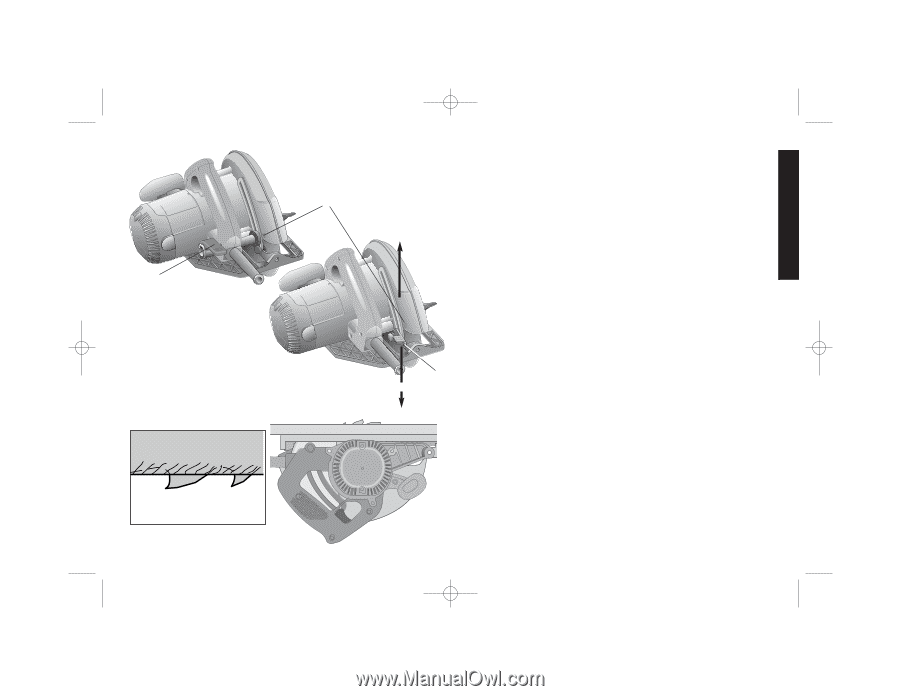
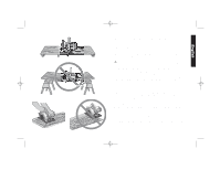
DW368/605266 7/2/02 11:50 AM Page 5 English B DW369 FIG. 5 FIG. 4 A FIG. 6 DW368 LOOSEN B TIGHTEN thread). Retract lower blade guard and remove blade. 3. When mounting new blade, the teeth must point in the direction of blade rotation. Replace outer clamp washer. Replace and tighten the blade bolt as much as possible with the fingers, then tighten firmly with the blade wrench. CUTTING DEPTH ADJUSTMENT (FIG. 4-6) DISCONNECT PLUG FROM POWER SUPPLY. Hold the saw firmly. Raise the depth adjustment lever Figure 4 (B) to loosen and move shoe to obtain the desired depth of cut, as shown. Make sure the depth adjustment lever has been retightened (lowered) before operating saw. Your saw is equipped with a carbide tipped saw blade for long life and efficient cutting. Setting the saw at the proper cutting depth keeps blade friction to a minimum, removes sawdust from between the blade teeth, results in cooler, faster sawing and reduces the chance of kickback. Align the appropriate mark on the depth adjustment strap with triangle on the upper blade guard.(Fig. 4)(A) Your depth is set. For the most efficient cutting action using a carbide tipped saw blade, set the Depth Adjustment so that about one half of a tooth projects below the surface of the wood to be cut (Figure 5). A method of checking for the correct cutting depth is shown in Figure 6. Lay a piece of the material you plan to cut along the side of the blade, as shown in the figure, and observe how much tooth projects beyond the material. BEVEL ANGLE ADJUSTMENT (DW368) FIG. 7 DISCONNECT THE SAW FROM THE POWER SUPPLY. The full range of the bevel adjustment is from 0 TO 56 DEGREES. The quadrant is graduated in increments of 5 degrees. On the front of the saw is a bevel angle adjustment mechanism consisting of a calibrated quadrant (A) and a knob. To set the saw for a bevel cut, turn the Bevel Adjustment knob (B) counterclockwise to 5
-
 1
1 -
2
-
 3
3 -
 4
4 -
 5
5 -
 6
6 -
 7
7 -
 8
8 -
 9
9 -
 10
10 -
 11
11 -
 12
12 -
 13
13 -
14
-
15
-
16
-
17
-
18
-
19
-
20
-
21
-
22
-
23
-
24
-
25
-
26
-
27
-
28
-
29
-
30
-
31
-
32
-
33
-
34
-
35
-
36
-
37
-
38
-
39
-
40
-
41
 |
 |