Dewalt DWE402N Instruction Manual - Page 16
Edge Grinding With Grinding Wheels Fig. 11, Surface Grinding With Grinding Wheels Fig. 10
 |
View all Dewalt DWE402N manuals
Add to My Manuals
Save this manual to your list of manuals |
Page 16 highlights
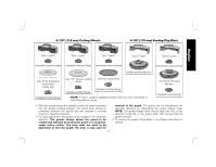
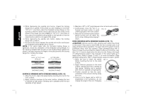
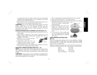
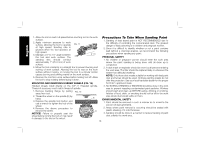
English 3. While depressing the spindle lock button, thread the locking flange (H) on spindle. If the wheel you are installing is more than 1/8" (3.17 mm) thick, place the threaded locking flange on the spindle so that the raised section (pilot) fits into the center of the wheel. If the wheel you are installing is 1/8" (3.17 mm) thick or less, place the threaded locking flange on the spindle so that the raised section (pilot) is not against the wheel. 4. While depressing the spindle lock button, tighten the locking flange with a wrench. 5. To remove the wheel, depress the spindle lock button and loosen the threaded locking flange with a wrench. NOTE: If the wheel spins after the threaded locking flange is tightened, check the orientation of the threaded locking flange. If a thin wheel is installed with the pilot on the locking flange against the wheel, it will spin because the height of the pilot prevents the locking flange from holding the wheel. FIG. 9 OVER 1/8" (3.17 mm) WHEELS 1/8" OR LESS (3.17 mm) WHEELS LOCKING FLANGE LOCKING FLANGE BACKING FLANGE BACKING FLANGE SURFACE GRINDING WITH GRINDING WHEELS (FIG. 10) 1. Allow the tool to reach full speed before touching the tool to the work surface. 2. Apply minimum pressure to the work surface, allowing the tool to operate at high speed. Grinding rate is greatest when the tool operates at high speed. 3. Maintain a 20° to 30° angle between the tool and work surface. 4. Continuously move the tool in a forward and back motion to avoid FIG. 10 creating gouges in the work surface. 5. Remove the tool from work surface before turning tool off. Allow the 20˚-30˚ tool to stop rotating before laying it down. EDGE GRINDING WITH GRINDING WHEELS (FIG. 11) CAUTION: Wheels used for edge grinding and cutting may break or kick back if they bend or twist while the tool is being used. In all edge grinding/cutting operations, the open side of the guard must be positioned away from the operator. Edge grinding/cutting with a Type 27 wheel must be limited to shallow cutting and notching-less than 1/2" (13 mm) in depth when the wheel is new. Reduce the depth of cutting/notching equal to the reduction of the wheel radius as it wears down. Refer to pages 10 and 11 for more information. Edge grinding/cutting with a Type 1 wheel requires usage of a Type 1 guard. 1. Allow the tool to reach full speed FIG. 11 before touching the tool to the work surface. 2. Apply minimum pressure to the work surface, allowing the tool to operate at high speed. Grinding rate is greatest when the tool operates at high speed. 3. Position yourself so that the openunderside of the wheel is facing away from you. 4. Once a cut is begun and a notch is established in the workpiece, do not change the angle of the cut. Changing 14
-
 1
1 -
2
-
3
-
4
-
5
-
6
-
7
-
8
-
9
-
10
-
 11
11 -
 12
12 -
 13
13 -
 14
14 -
 15
15 -
 16
16 -
 17
17 -
 18
18 -
 19
19 -
 20
20 -
 21
21 -
22
-
23
-
24
-
25
-
26
-
27
-
28
-
29
-
30
-
31
-
32
-
33
-
34
-
35
-
36
-
37
-
38
-
39
-
40
-
41
-
42
-
43
-
44
-
45
-
46
-
47
-
48
-
49
-
50
-
51
-
52
-
53
-
54
-
55
-
56
-
57
-
58
-
59
-
60
-
61
-
62
-
63
-
64
-
65
-
66
-
67
-
68
-
69
-
70
-
71
-
72
 |
 |
