Dewalt DWE402N Instruction Manual - Page 17
Using Sanding Backing Pads, Fig. 14, Surface Finishing With Sanding Flap Discs Fig. 12, Mounting
 |
View all Dewalt DWE402N manuals
Add to My Manuals
Save this manual to your list of manuals |
Page 17 highlights
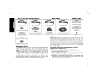
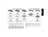
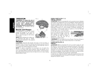
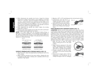
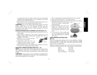
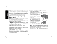
English the angle will cause the wheel to bend and may cause wheel breakage. Edge grinding wheels are not designed to withstand side pressures caused by bending. 5. Remove the tool from the work surface before turning the tool off. Allow the tool to stop rotating before laying it down. WARNING: Do not use edge grinding/cutting wheels for surface grinding applications if the wheel label has forbidden such use because these wheels are not designed for side pressures encountered with surface grinding. Wheel breakage and serious personal injury may result. SURFACE FINISHING WITH SANDING FLAP DISCS (FIG. 12) 1. Allow the tool to reach full speed before touching the tool to the work surface. 2. Apply minimum pressure to work surface, allowing the tool to operate at high speed. Sanding rate is greatest when the tool operates at high speed. 3. Maintain a 5° to 10° angle between FIG. 12 the tool and work surface. 4. Continuously move the tool in a forward and back motion to avoid 5˚-10˚ creating gouges in the work surface. 5. Remove the tool from work surface before turning tool off. Allow the tool to stop rotating before laying it down. MOUNTING SANDING BACKING PADS (FIG. 1, 13) NOTE: Use of a guard with sanding discs that use backing pads, often called fiber resin discs, is not required. Since a guard is not required for these accessories, the guard may or may not fit correctly if used. WARNING: Proper guard must be reinstalled for grinding wheel, cutting wheel, sanding flap disc, wire brush or wire wheel applications after sanding applications are complete. 1. Place or appropriately thread backing pad (O) on the spindle. 2. Place the sanding disc (P) on the backing pad (O). 3. While depressing spindle lock (D), thread clamp nut (Q) on spindle, piloting the raised hub on the clamp FIG. 13 nut into the center of sanding disc Q and backing pad. 4. Tighten the clamp nut by hand. Then depress the spindle lock button P while turning the sanding disc until the sanding disc and clamp nut are snug. 5. To remove the wheel, grasp and O turn the backing pad and sanding pad while depressing the spindle lock button. USING SANDING BACKING PADS (FIG. 14) Choose the proper grit sanding discs for your application. Sanding discs are available in various grits. Coarse grits yield faster material removal rates and a rougher finish. Finer grits yield slower material removal and a smoother finish. Begin with coarse grit discs for fast, rough material removal. Move to a medium grit paper and finish with a fine grit disc for optimal finish. Coarse 16-30 grit Medium 36-80 grit Fine Finishing 100-120 grit Very Fine Finishing 150-180 grit 15
-
 1
1 -
2
-
3
-
4
-
5
-
6
-
7
-
8
-
9
-
10
-
11
-
 12
12 -
 13
13 -
 14
14 -
 15
15 -
 16
16 -
 17
17 -
 18
18 -
 19
19 -
 20
20 -
 21
21 -
 22
22 -
23
-
24
-
25
-
26
-
27
-
28
-
29
-
30
-
31
-
32
-
33
-
34
-
35
-
36
-
37
-
38
-
39
-
40
-
41
-
42
-
43
-
44
-
45
-
46
-
47
-
48
-
49
-
50
-
51
-
52
-
53
-
54
-
55
-
56
-
57
-
58
-
59
-
60
-
61
-
62
-
63
-
64
-
65
-
66
-
67
-
68
-
69
-
70
-
71
-
72
 |
 |
