Dewalt DWE4214 Instruction Manual - Page 13
/2 115 mm Cutting Wheels, 1/2 115 mm Sanding Flap Discs
 |
View all Dewalt DWE4214 manuals
Add to My Manuals
Save this manual to your list of manuals |
Page 13 highlights
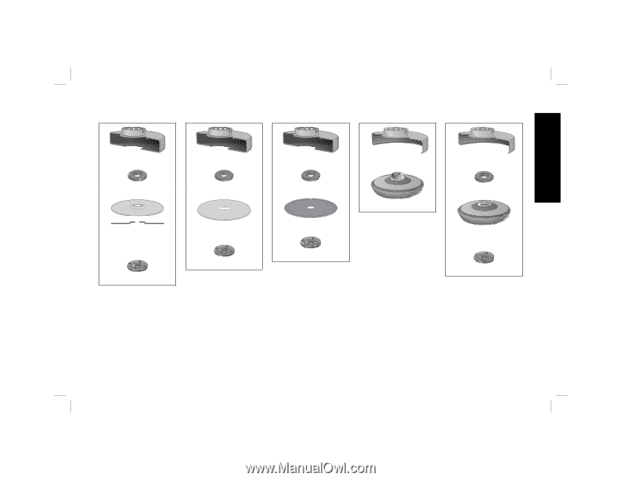
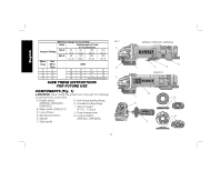
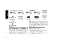
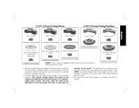
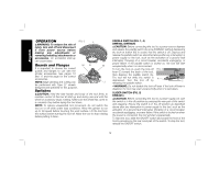
4-1/2" (115 mm) Cutting Wheels 4-1/2" (115 mm) Sanding Flap Discs English Type 1 guard* Type 1 guard* Type 1 guard* Type 27 guard Type 27 guard unthreaded backing flange unthreaded backing flange unthreaded backing flange unthreaded backing flange hubbed sanding flap disc Type 27/42 depressed center wheel, cutting only threaded locking flange Type 1/41 abrasive cutting wheel diamond cutting wheel threaded locking flange threaded locking flange * NOTE: A Type 1 guard is available at extra cost from your local dealer or authorized service center. non-hubbed sanding flap disc threaded locking flange 4. With the spindle facing the operator, rotate the guard clockwise into the desired working position. The guard body should be positioned between the spindle and the operator to provide maximum operator protection. 5. For easy adjustment, the guard can be rotated in the clockwise direction. The guards design allows the guard to be rotated and adjusted by turning the guard in a clockwise, single action motion. The lever does not need to be depressed to turn the guard. The lever is only used for 11 removal of the guard. The guard can be repositioned the opposite direction by depressing the guard release lever. NOTE: The guard release lever should snap into one of the alignment holes (N) on the guard collar. This ensures that the guard is secure. 6. To remove the guard, follow steps 1-3 of these instructions in reverse.
-
 1
1 -
2
-
3
-
4
-
5
-
6
-
7
-
 8
8 -
 9
9 -
 10
10 -
 11
11 -
 12
12 -
 13
13 -
 14
14 -
 15
15 -
 16
16 -
 17
17 -
 18
18 -
19
-
20
-
21
-
22
-
23
-
24
-
25
-
26
-
27
-
28
-
29
-
30
-
31
-
32
-
33
-
34
-
35
-
36
-
37
-
38
-
39
-
40
-
41
-
42
-
43
-
44
-
45
-
46
-
47
-
48
-
49
-
50
-
51
-
52
-
53
-
54
-
55
-
56
-
57
-
58
-
59
-
60
-
61
-
62
-
63
-
64
-
65
-
66
-
67
-
68
-
69
-
70
-
71
-
72
 |
 |