EMC AX150 Product Guide - Page 7
The AX Series hardware architecture and specifications - navisphere
 |
View all EMC AX150 manuals
Add to My Manuals
Save this manual to your list of manuals |
Page 7 highlights
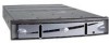
Table 1. Comparison of AX Series and CX Series storage systems AX150SC AX150 CX300 Storage controllers Single Dual Dual Enclosure 2U rack 2U rack 4U rack Cache memory (per controller) 512 MB 512 MB 1 GB Cache configuration Battery backed Mirrored Mirrored Minimum drive count 3 4 5 Maximum drive count 12 SATA II 12 SATA II 60 FC or ATA Front-end host ports Maximum virtual disks (LUNs) 2 x 2 Gb Fibre Channel 256 4 x 2 Gb Fibre Channel 256 4 x 2 Gb Fibre Channel 512 Maximum disk pools (RAID groups) 4 4 256 Maximum initiators (host ports) 10 20 128 Maximum HA hosts 5 10 256 Snapshot sources per storage system 8 8 150 Snapshots per source 1 1 8 MirrorView™ N/A N/A CX3-20/CX3-40 SnapView clones N/A N/A Yes SAN Copy™ Yes* Yes* Yes* Navisphere Manager Supported as an Supported as an Yes upgrade feature upgrade feature * Adding SAN Copy/E software to the AX150 provides the ability to replicate data from the AX150 with Navisphere. The AX Series hardware architecture and specifications The AX150 architecture is designed for redundancy, and the dual-controller model for high availability. The next sections describe the architecture main components of the AX150 storage system. The AX150 enclosure The AX150 is 3.4 inches (8.68 cm) high by 17.7 inches (45 cm) wide by 24.5 inches (62.3 cm) deep. The AX150 SATA II drives and storage processors (SPs) are both contained within this 2U enclosure. Up to twelve drives can be inserted behind the bezel into the front of the storage system and are configured in three parallel rows of four drives each. Drives 0-3 are used for system-specific code and database information, but contain user space as well. The minimum configuration for the single-controller AX150SC is three drives (slots 0-2 must be full). For a dual-controller system, drive slots 0-3 must contain drives. Slot 0 is in the upper left of the storage system and numbering proceeds left to right. Drive fillers must be inserted in unused drive slots to ensure proper cooling of the storage system. Up to five fans are located directly behind the drives and pull air from the front of the storage system and across the drives. One fan per SP is also provided to maintain an appropriate operating temperature. Figure 1 on page 8 shows the front view of the drives and system LEDs in the AX150. Introduction to the AX150 Storage System A Detailed Review 7
-
 1
1 -
 2
2 -
 3
3 -
 4
4 -
 5
5 -
 6
6 -
 7
7 -
 8
8 -
 9
9 -
 10
10 -
 11
11 -
 12
12 -
13
-
14
-
15
-
16
-
17
-
18
-
19
-
20
-
21
-
22
-
23
-
24
 |
 |
