EMC AX150 Product Guide - Page 8
Storage processor assembly details - cache memory card
 |
View all EMC AX150 manuals
Add to My Manuals
Save this manual to your list of manuals |
Page 8 highlights
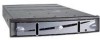
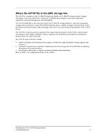
Enclosure Fault LED (Amber) Disk Slot 0 Disk Slot 8 Enclosure Power LED (Blue) Disk Slot 3 Disk Status LED (Blue = Activity Amber = Fault) Disk Slot 11 Figure 1. AX150 Enclosure front view Storage processor assembly details The SPs intercept and manage I/O from servers to the drives in the storage system. The AX150SC contains a single SP. The AX150 is a dual-controller model that provides full redundancy and true high availability at the component level. There is no distinction between the single SP used in the AX150SC and those included in the AX150. The back half of the AX150 enclosure contains the SP assembly, or suitcase. This removable component houses the controllers, system fans, power supplies, memory cards, and Fibre Channel personality cards for the storage system. Each controller has one power supply associated with it. In the case of a single power supply failure, the remaining power supply provides power to both SPs in the system. The single controller AX150SC has the option of having a second power supply to provide redundancy. The whole assembly may be removed from the unit by unlocking the latches at either side of the assembly and sliding the suitcase out of the enclosure. The AX150 can be rack-mounted in any 19-inch NEMA-standard 40U cabinets. Figure 2 on page 9 and Figure 3 on page 10 show detailed views of the back of the AX150 enclosures. Each SP is powered by an Intel Socket 370 Celeron processor and has 512 MB of cache available on a dual inline-memory module (DIMM). The AX150SC supports mirroring this write cache to a 256 MB, 33 MHz PCI-based battery-backed cache module (BBCM), whose three indicator LEDs are visible in Figure 2 on page 9 on the left side of the enclosure. This BBCM can hold live data for up to 96 hours, allowing a user to replace a failed SP or to reapply power to the storage system. In the dual-SP configuration, the BBCM module is replaced by a second SP with an identical DIMM card to provide for mirroring of its peer SP's cache. The remaining SP memory is allocated as 136 MB of write cache and 36 MB of read cache. Each SP contains two small form-factor, 2 Gb/s optical front-end ports for server connectivity. All Fibre Channel I/O traverses a 64-bit, 100-MHz PCI bus to the two available SATA drive controllers. Each SP has access over its own bus to the SATA drives in the array, providing redundant back-end loops for disk connectivity. The assembly components also include two RJ45 connectors. One connector is a serial port for service purposes, and the other a 10/100/1000 Ethernet port for storage system management. An integrated UPS (purchased with the AX150i) provides battery-backed power to the storage system should power fail to both power supplies. The UPS allows the storage system to remain up and running by dumping cache to the vault drives, disabling write caching and maintaining power to SP A. Introduction to the AX150 Storage System A Detailed Review 8
-
 1
1 -
2
-
 3
3 -
 4
4 -
 5
5 -
 6
6 -
 7
7 -
 8
8 -
 9
9 -
 10
10 -
 11
11 -
 12
12 -
 13
13 -
14
-
15
-
16
-
17
-
18
-
19
-
20
-
21
-
22
-
23
-
24
 |
 |
