Electrolux EWMGD65HIW Installation Instructions - Page 5
Immo/Hatay
 |
UPC - 012505379017
View all Electrolux EWMGD65HIW manuals
Add to My Manuals
Save this manual to your list of manuals |
Page 5 highlights
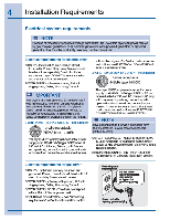
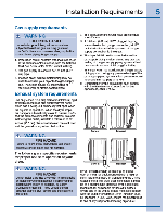
Installation Requirements 5 Gas supply requirements 1, WARNING EXPLOSION HAZARD Uncoated copper tubing Wll corr000 when subJectea t0 natural oas. caasin3 oas leaks. Use ONLY black iron. stainless steel. or plasticcoated brass piping for gas supply. 1 installation MUST contom with local codes, or in tne absence of local coles, with the National Fuel Gas Code, ANSI Z223.1 (latest edition). 2 The gas supply line should be 1/2 Inch (1.27 cm) pipe. 3 it codes allow. neAlble metal tubing may be used to connect yourdryertothe Gas supply line. The tubing MUST be constructed of stainless steel or pastic-o3ated brass. Exhaust system requirements 4. The gas supply Ilne MUST -rave an Individual shutoff valve. 5. A 1/8 inch ((.92 cm) N.P.T. plugged tapping, accessibletor test gauge connection. MUST he Installed Immo/Hatay upstream O1tha pas supply connection to the dryer. e. The aryer MUST be disconnected tI0M the gas supply piping system curing any pressure testing of tne gas supply raping system at test pressures in excess of 1/2 psig (3.45 lea). 7. The dryer MUST be Isolatec 'nom the gas supply piping system during any pressure testing of the gas supply piping system al test pressures equal to or lessthan 1/2 pslg (3.45 kPa). U. connectionsfortne gas sup must comply with tne Standard for Connactois tor Gas Appta7ces, ANSI 22124. Use only 4 Inch (10.2 ctm dianeter (minimum) o'llexible metal duct ant approved vent hood which has a swing-cut damper(s) bet cpen when the dryer is in operation. When the dryer stop, the dampers automatically CMG to prevent drafts ma the entrance of Inaeota one rolenta. To avoid lastitctIng the outlet, maintain a minimum of 12 tales (30.5 an) clearance between the vent hood aid the ground or any other obstruction. ,1\ WARNING FIRE HAZARD 1 Failure 10 follow mese instrolons can create ofteSSIve drying times an0 ire hazards. L reeembet The following are specific requirements for proper and safe operation of your dryer. WARNING FIRE HAZARD Do not Install a oomes dryer with flexible plastic or metal fon val1Ing MaterlaS. Flexible venting matenais are known to collapse. be easily crusneo anu trap lint. These conditicrts WIII obstruct cronies dryer alma,' and increase the liSk 01lire. 4. Coned c:b 6h kcanct If present system Is made up of Masts MO or metal foil duct replace it with a rigid or sell-rigid metal duct. In Canada and the United Mates If metal (toll type) duct is installed, It must beot a specific type reconnect by the appliance manufacturer as suitable for usewith clothes dryers am In the United States must also comply wth the Otrtlinetor Clothes Dryer 1Tansition Duct, UL standard 2158A. Also, ensure the present eruct is 'nee of any lint prior to instal ing dryer duct.
-
 1
1 -
 2
2 -
 3
3 -
 4
4 -
 5
5 -
 6
6 -
 7
7 -
 8
8 -
 9
9 -
 10
10 -
 11
11 -
12
-
13
-
14
-
15
-
16
-
17
-
18
-
19
-
20
-
21
-
22
-
23
-
24
 |
 |
