Electrolux GLMV169HS Installation Instructions - Page 3
Tools Recommended For, Installation, Installation Hardware, Preparation Of The Oven
 |
View all Electrolux GLMV169HS manuals
Add to My Manuals
Save this manual to your list of manuals |
Page 3 highlights
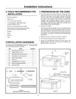
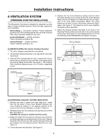
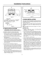
Installation Instructions 5 TOOLS RECOMMENDED FOR INSTALLATION • Phillips Screwdriver • Electric Drill • 1/2", 5/8" and 3/32" Drill Bits • 1-1/2" Wood Bit or Metal Hole Cutter (if metal cabinet is used) • Saw to cut exhaust opening (if needed) • Protective Drop Cloth for product and range - you may also use carton for protection • Scissors • Pencil • Measure • Tape 6 INSTALLATION HARDWARE The INSTALLATION HARDWARE (items 1 - 8) packed with the oven should contain the following: Item Name 1 Wood Screw 5 X 30 mm 2 Toggle Bolt 3/16 inch 3 Top Cabinet Screw 5 X 60 mm 4 Flat Washer 30 mm diameter 5 Power Cord Hanger 6 Grommet 7 Tapping Screw 4 x 12 mm 8 Exhaust Damper Assembly 9 Charcoal Filter Quantity 6 4 2 2 1 1 4 1 1 7 PREPARATION OF THE OVEN 1. Open the bottom of the carton, bend the carton flaps back and tilt the oven over to rest on plastic foam pad. Lift carton off oven and remove all packing materials, Installation Instructions, Wall Template, Top Template, Charcoal Filter, Turntable and Turntable Support; however, DO NOT REMOVE THE WAVEGUIDE COVER, which is located on the ceiling in the oven cavity. SAVE THE CARTON AS IT MAY MAKE INSTALLATION EASIER. 2. CHECK THE OVEN. Check the oven for any damage, such as misaligned or bent door, damaged door seals and sealing surfaces, broken or loose door hinges and latches and dents inside the cavity or on the door. If there is any damage, do not operate the oven and contact your dealer or ELECTROLUX AUTHORIZED SERVICER. 3. Remove and save Screws (A) as shown in Figure 5. 4. Pull the louver away from the unit and set aside. 5. Loosen the two Mounting Screws (D) which secure the Mounting Plate to the rear side of the oven. Remove the Mounting Plate. See Figure 6. (A) (A) (A) (A) Mounting Plate Control Panel Side Figure 5 Mounting Plate (D) (D) Figure 4 Parts shown not to common scale. 3 Figure 6
-
 1
1 -
 2
2 -
 3
3 -
 4
4 -
 5
5 -
 6
6 -
 7
7 -
 8
8
 |
 |
