Epic Fitness E 760 Elliptical English Manual - Page 6
Ramp Axle Cover onto an M6 x 16mm Button Screw
 |
View all Epic Fitness E 760 Elliptical manuals
Add to My Manuals
Save this manual to your list of manuals |
Page 6 highlights
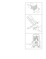
2. While another person lifts the rear of the Frame (1), attach the Rear Stabilizer (30) to the Frame with two 2 M10 x 105mm Button Screws (89). 30 1 3. Identify the Ramp Axle (39), which is the longest axle. Next, identify the Ramp Axle Covers (41), which are smaller than the Wheel Covers (not shown). Slide a Ramp Axle Cover onto an M6 x 16mm Button Screw (103) as shown, and tighten the Button Screw into one end of the Ramp Axle. Next, apply a small amount of the included grease to the Ramp Axle. Have a second person hold the two Ramp Spacers (42) against the indicated tubes on the Frame (1). Align the tubes on the Ramp (33) with the Ramp Spacers; make sure that the Ramp is turned as shown. Insert the open end of the Ramp Axle (39) into the Ramp, the Ramp Spacers, and the Frame. If necessary, tap the Ramp Axle with a rubber mallet to insert it. Slide the other Ramp Axle Cover (41) onto an M6 x 16mm Button Screw (103), and tighten the Button Screw into the open end of the Ramp Axle (39). 4. Slide an M6 Washer (102) onto an M6 x 16mm Button Screw (103), and tighten the Button Screw into one end of the Lift Axle (38). Next, apply a small amount of grease to the Lift Axle. Raise the Ramp (33). Insert the Lift Axle (38) through the welded tube under one side of the Ramp, through the motor screw, and then through the welded tube under the other side of the Ramp. As you insert the Incline Axle through the motor screw, make sure that the motor screw does not turn. Slide an M6 Washer (102) onto an M6 x 16mm Button Screw (103), and tighten the Button Screw into the open end of the Lift Axle (38). 89 3 Tubes 103 33 Grease 39 103 41 41 42 42 Tubes 1 4 33 Motor Screw 103 38 103 102 Grease 102 6
-
 1
1 -
 2
2 -
 3
3 -
 4
4 -
 5
5 -
 6
6 -
 7
7 -
 8
8 -
 9
9 -
 10
10 -
 11
11 -
 12
12 -
13
-
14
-
15
-
16
-
17
-
18
-
19
-
20
-
21
-
22
-
23
-
24
 |
 |
