Epson 680Pro Service Manual - Page 77
Since the cable between C383 MAIN board and C383 PSB/E, PS board fixing screws
 |
UPC - 010343832138
View all Epson 680Pro manuals
Add to My Manuals
Save this manual to your list of manuals |
Page 77 highlights
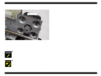
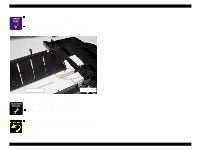
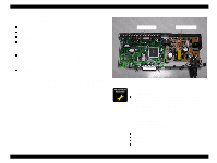
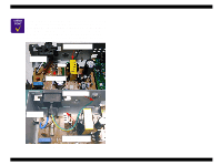
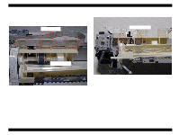
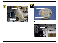
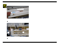
EPSON Stylus COLOR 680/777/777i Revision B n Since the cable between C383 MAIN board and C383 PSB/E board are directly soldered, take the following steps when replacing only one circuit board in the service activity. 1. Take off the cable on the Main board by removing the solder by heating it with the soldering iron. 2. Replace the defective circuit board with new one. 3. Insert the tip of the cable into the soldering hole of the ASP Main n board and solder it securely. Tightening Torque for screw • C.B.S 3x6 F/Zn screw for PS board : 6+/- 1kgf.cm • C.B.S-TITE R 3x6 F/Uc screw for PS board : 6+/- 1kgf.cm • C.B.S 3x6 F/Zn screw for Main board : 6+/- 1kgf.cm • C.P. 3x6 F/Zn screw for Parallel I/F connector : 6+/- 1kgf.cm • C.B.S 3x6 F/Zn screw for Circuit unit : 6+/- 1kgf.cm • C.B.(O) 4x5 F/ZG screw for Earth cable : 11+/-1kgf.cm CHECK P O IN T When replacing or removing the PS board, be sure to use the following suitable screw to secure the PS board. C.B.S-TITE R 3x6, F/UC Figure 4-18. PS board fixing screws n Install a new cartridge before sending back the printer to the user, since the ink cartridge once taken out can not be used n again. Installation of I/C must be carried out by I/C replacement sequence. Otherwise, ink may not eject properly. Disassembly and Assembly Disassembly 77
-
 1
1 -
2
-
3
-
4
-
5
-
6
-
7
-
8
-
9
-
10
-
11
-
12
-
13
-
14
-
15
-
16
-
17
-
18
-
19
-
20
-
21
-
22
-
23
-
24
-
25
-
26
-
27
-
28
-
29
-
30
-
31
-
32
-
33
-
34
-
35
-
36
-
37
-
38
-
39
-
40
-
41
-
42
-
43
-
44
-
45
-
46
-
47
-
48
-
49
-
50
-
51
-
52
-
53
-
54
-
55
-
56
-
57
-
58
-
59
-
60
-
61
-
62
-
63
-
64
-
65
-
66
-
67
-
68
-
69
-
70
-
71
-
 72
72 -
 73
73 -
 74
74 -
 75
75 -
 76
76 -
 77
77 -
 78
78 -
 79
79 -
 80
80 -
 81
81 -
 82
82 -
83
-
84
-
85
-
86
-
87
-
88
-
89
-
90
-
91
-
92
-
93
-
94
-
95
-
96
-
97
-
98
-
99
-
100
-
101
-
102
-
103
-
104
-
105
-
106
-
107
-
108
-
109
-
110
-
111
-
112
-
113
-
114
-
115
-
116
-
117
-
118
-
119
-
120
-
121
-
122
-
123
-
124
-
125
-
126
-
127
-
128
-
129
-
130
-
131
-
132
-
133
-
134
-
135
-
136
-
137
-
138
-
139
-
140
-
141
-
142
-
143
-
144
-
145
 |
 |
