Epson 680Pro Service Manual - Page 93
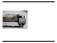
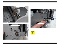
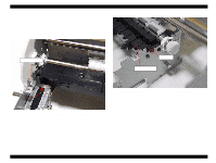
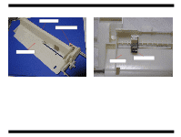
Grounding plate assembling position, CR timing belt setting position
 |
UPC - 010343832138
View all Epson 680Pro manuals
Add to My Manuals
Save this manual to your list of manuals |
Page 93 highlights
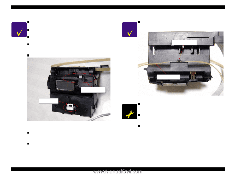
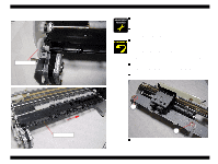
EPSON Stylus COLOR 680/777/777i Revision B CHECK P O IN T n Unlike the previous products, the oil pad is not built in the CR n unit. Make sure that the tips of the CR guide shaft rod springs are set n in the holes in the Main frame. Make sure that the CR guide shaft rod springs are correctly set n in the suitable position. Refer to Figure 4-44,Figure 4-45. If you disassemble the CR unit after removing the CR unit from the printer, make sure that the CR Grounding plate is assembled n in the suitable position in the CR unit. Refer to Figure 4-47. .Make sure that the CR slider is assembled on the CR unit. CHECK P O IN T n If the CR unit is disassembled or replaced with a new one, make sure that the CR timing belt is set in the assembling groove correctly as following figure. Assembling groove CR timing belt CR slider CR Grounding plate Figure 4-47. Grounding plate assembling position n If you remove the Printhead from the CR unit, make sure that the Head grounding plate is set in the CR unit. Refer to n Figure4-9. Make sure that the groove on the CR guide shaft must be set to the left side. Figure 4-48. CR timing belt setting position n A D J U S T M E N T When you replace the CR unit with a new one, lubricate it with R E Q U IR E D the suitable amount of the G-55 grease by the specified position. n Refer to Chapter 6 Figure 6-4. When you replace the CR Pulley shaft with new one, lubricate it with the suitable amount of G-26 grease by the specific position. n Refer to Chapter 6 Figure6-3. When removing or replacing the CR unit with a new one, adjust the Gap (Bi-d). Disassembly and Assembly Disassembly 93
-
 1
1 -
2
-
3
-
4
-
5
-
6
-
7
-
8
-
9
-
10
-
11
-
12
-
13
-
14
-
15
-
16
-
17
-
18
-
19
-
20
-
21
-
22
-
23
-
24
-
25
-
26
-
27
-
28
-
29
-
30
-
31
-
32
-
33
-
34
-
35
-
36
-
37
-
38
-
39
-
40
-
41
-
42
-
43
-
44
-
45
-
46
-
47
-
48
-
49
-
50
-
51
-
52
-
53
-
54
-
55
-
56
-
57
-
58
-
59
-
60
-
61
-
62
-
63
-
64
-
65
-
66
-
67
-
68
-
69
-
70
-
71
-
72
-
73
-
74
-
75
-
76
-
77
-
78
-
79
-
80
-
81
-
82
-
83
-
84
-
85
-
86
-
87
-
 88
88 -
 89
89 -
 90
90 -
 91
91 -
 92
92 -
 93
93 -
 94
94 -
 95
95 -
 96
96 -
 97
97 -
 98
98 -
99
-
100
-
101
-
102
-
103
-
104
-
105
-
106
-
107
-
108
-
109
-
110
-
111
-
112
-
113
-
114
-
115
-
116
-
117
-
118
-
119
-
120
-
121
-
122
-
123
-
124
-
125
-
126
-
127
-
128
-
129
-
130
-
131
-
132
-
133
-
134
-
135
-
136
-
137
-
138
-
139
-
140
-
141
-
142
-
143
-
144
-
145
 |
 |