Epson BrightLink 536Wi Installation Guide - Short-Throw Wall Mount (ELPMB45)
Epson BrightLink 536Wi Manual
 |
View all Epson BrightLink 536Wi manuals
Add to My Manuals
Save this manual to your list of manuals |
Epson BrightLink 536Wi manual content summary:
- Epson BrightLink 536Wi | Installation Guide - Short-Throw Wall Mount (ELPMB45) - Page 1
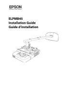
ELPMB45 Installation Guide Guide d'installation - Epson BrightLink 536Wi | Installation Guide - Short-Throw Wall Mount (ELPMB45) - Page 2
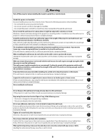
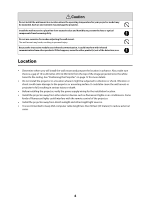
About This Installation Guide This guide describes how to mount the short-throw projectors BrightLink® 536Wi and PowerLite® 520/525W/ 530/535W to a wall using the Epson® wall mount. Not all models are available in all markets. Safety Instructions For your safety, read all the instructions in this - Epson BrightLink 536Wi | Installation Guide - Short-Throw Wall Mount (ELPMB45) - Page 3
. Install the wall mount so that it can sufficiently support the weight of the projector and wall mount, and resist any horizontal vibration. Use M8 nuts and bolts. Nuts and bolts smaller than M8 could cause the wall mount to fall. Epson accepts no responsibility for any damage or injury caused by - Epson BrightLink 536Wi | Installation Guide - Short-Throw Wall Mount (ELPMB45) - Page 4
the projector. Install the wall mount in a place free from excessive dust and humidity to prevent the lens or optical components from becoming dirty. Do not use excessive force when adjusting the wall mount. The wall mount may break, resulting in personal injury. Because the interactive module - Epson BrightLink 536Wi | Installation Guide - Short-Throw Wall Mount (ELPMB45) - Page 5
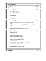
1 Package Contents s6 2 Specifications s7 3 Connecting Devices 1. Connecting Computers 2. Connecting Through a Network 3. Connecting Document Cameras 4. Using a Switch Box 5. Connecting Video Equipment 6. Connecting Audio s8 4 Positioning the Projector s 13 1. Installation Measurements for - Epson BrightLink 536Wi | Installation Guide - Short-Throw Wall Mount (ELPMB45) - Page 6
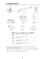
Package Contents Adjustment Arm unit Arm plate Projector attachment plate Wall plate Wall plate 7 • Use the bolts or screws supplied with the wall mount to install it as directed in this guide. Do not substitute these bolts with any other types. • You need to use commercially available M8 × - Epson BrightLink 536Wi | Installation Guide - Short-Throw Wall Mount (ELPMB45) - Page 7
2 Specifications Item Specification Weight Approx. 24 lb (11 kg) Maximum load capacity 12.1 lb (5.5 kg) Arm length 59.4 inches (1510 mm) (from wall plate attachment point to arm - Epson BrightLink 536Wi | Installation Guide - Short-Throw Wall Mount (ELPMB45) - Page 8
location where the wall mount is to be installed. Interactive models also require a USB cable. Make sure you projector. This includes cables for any optional equipment that may be connected in the future. For details, refer to the online User's Guide or at epson.com/support (U.S.) or epson.ca/support - Epson BrightLink 536Wi | Installation Guide - Short-Throw Wall Mount (ELPMB45) - Page 9
an iPad, iPhone, or iPod touch using the optional Epson iProjection™ app. When the projector is connected to these devices, only the built-in toolbar is available (single pen support). Wireless router or access point Wireless network connection with interactivity using the built-in toolbar If the - Epson BrightLink 536Wi | Installation Guide - Short-Throw Wall Mount (ELPMB45) - Page 10
computer's USB port, as shown below. This will enable full interactivity and dual pen support (using Easy Interactive Tools software) on the document camera image. To projector Although you can connect the Epson DC-06 directly to the projector's TypeA port using a USB cable, this will provide only - Epson BrightLink 536Wi | Installation Guide - Short-Throw Wall Mount (ELPMB45) - Page 11
Connecting Audio A variety of audio connections are available: • You can connect a dynamic microphone to the Mic port and output the sound through the projector. • You can also output computer audio. If you connected the computer using a VGA cable, you need to connect an optional 3.5 mm stereo mini - Epson BrightLink 536Wi | Installation Guide - Short-Throw Wall Mount (ELPMB45) - Page 12
4 Positioning the Projector BrightLink 536Wi and PowerLite 525W/535W can project up to 113 to the tables on the following pages and install the mount and projector to project images at the appropriate size. The values are only a guide. The recommended projection distance is 27.6 to 46.9 inches (70 - Epson BrightLink 536Wi | Installation Guide - Short-Throw Wall Mount (ELPMB45) - Page 13
Installation Measurements for PowerLite 525W/535W and BrightLink 536Wi - Wide Screen size Minimum projection distance (A)* 16:10 WXGA 4:3 XGA 16:9 Widescreen Vertical angle adjustment (B)** Distance from top of image to ceiling (C) Distance from top - Epson BrightLink 536Wi | Installation Guide - Short-Throw Wall Mount (ELPMB45) - Page 14
Screen size 16:10 WXGA 4:3 XGA Minimum projection distance (A)* Vertical angle adjustment (B)** Distance from top of image to ceiling (C) Distance from top of image to center of lens (D) Minimum projection distance (A)* Vertical angle adjustment (B)** Distance from top of image to ceiling - Epson BrightLink 536Wi | Installation Guide - Short-Throw Wall Mount (ELPMB45) - Page 15
- - 113 in. 46.9 in. (119 cm) 2.8 in. (7 cm) 20.1 in. (51 cm) 7.1 in. (18 cm) - - - - - - - * Projection distance is measured from the projector lens to the projection surface. ** Vertical adjustments are made with the vertical angle adjustment screw. (See item "E" in the image on page 12). - Epson BrightLink 536Wi | Installation Guide - Short-Throw Wall Mount (ELPMB45) - Page 16
Installation Measurements for PowerLite 525W/535 W and BrightLink 536Wi - Tele Screen size range Projection distance range (A) Vertical adjustment range (B) Distance from top of projected image to ceiling range (C) 16:10 WXGA* 50 - 84 in. - Epson BrightLink 536Wi | Installation Guide - Short-Throw Wall Mount (ELPMB45) - Page 17
Installation Measurements for PowerLite 520/530 - Wide 17 Screen size Minimum projection distance (A)* 16:10 WXGA Vertical angle adjustment (B)** Distance from top of image to ceiling (C) Distance from top of image to center of lens (D) Minimum projection distance (A)* 4:3 XGA Vertical - Epson BrightLink 536Wi | Installation Guide - Short-Throw Wall Mount (ELPMB45) - Page 18
Screen size Minimum projection distance (A)* 16:10 WXGA Vertical angle adjustment (B)** Distance from top of image to ceiling (C) Distance from top of image to center of lens (D) Minimum projection distance (A)* 4:3 XGA Vertical angle adjustment (B)** Distance from top of image to ceiling - Epson BrightLink 536Wi | Installation Guide - Short-Throw Wall Mount (ELPMB45) - Page 19
- - 106 in. - - - - 46.9 in. (119 cm) 0.8 in. (2 cm) 18.9 in. (48 cm) 5.5 in. (14 cm) - - - * Projection distance is measured from the projector lens to the projection surface. ** Vertical adjustments are made with the vertical angle adjustment screw. (See item "E" in the image on page 12). - Epson BrightLink 536Wi | Installation Guide - Short-Throw Wall Mount (ELPMB45) - Page 20
Installation Measurements for PowerLite 520/530 - Tele 16:10 WXGA* 4:3 XGA** 16:9 Widescreen* Screen size range Projection distance range (A) 44 - 74 in. 46 - 78 in. 43 - 72 in. 27.6 - 46.9 in. (70 - 119 cm) 27.2 - 46.5 in. (69 - 118 cm) 27.6 - 46.9 in. (70 - 119 cm) Vertical adjustment range - Epson BrightLink 536Wi | Installation Guide - Short-Throw Wall Mount (ELPMB45) - Page 21
If you have a pre-existing interactive whiteboard, refer to the table below to identify common models and sizes. If your board is listed here, use the dimensions to reference the installation requirements found on pages 13 through 20. Diagonal size specification 57 inches 60 inches 63 inches 64 - Epson BrightLink 536Wi | Installation Guide - Short-Throw Wall Mount (ELPMB45) - Page 22
can sufficiently support the weight of the projector and wall mount, and resist any horizontal vibration. Use M8 nuts and bolts. Nuts and bolts smaller than M8 could cause the wall mount to fall. ❏ Epson cm) gap (PowerLite 525W/535W and BrightLink 536Wi) or a 5.5 inch (14 cm) gap - Epson BrightLink 536Wi | Installation Guide - Short-Throw Wall Mount (ELPMB45) - Page 23
3. Position the wall plate over the marks you made in step 1, and then mark the position of the wall plate's mounting holes as shown in the following illustration. Use at least three mounting holes. If you are securing the wall plate in four places, drill the holes indicated by A or B in the - Epson BrightLink 536Wi | Installation Guide - Short-Throw Wall Mount (ELPMB45) - Page 24
position of the adjustment unit screws (B) if you are using the wall mount with a product other than the PowerLite 520/525W/530/535W or BrightLink 536Wi projectors. Arm unit M4 × 12 mm hexagon socket head cap bolt M8 × 16 mm hexagon socket head cap bolt Adjustment unit 3. Attach the arm plate - Epson BrightLink 536Wi | Installation Guide - Short-Throw Wall Mount (ELPMB45) - Page 25
cables. Arm unit Vertical adjustment screw Caution Problems may occur if you use this product without routing the cables through the arm unit. q Route the USB cable so that the type B connector emerges on the projector side. Epson recommends labeling any duplicate cables so that additional - Epson BrightLink 536Wi | Installation Guide - Short-Throw Wall Mount (ELPMB45) - Page 26
(M4) and five M4 × 12 mm bolts with washers/spring washers. Attachment plate M4 × 12 mm hexagon socket head cap bolt with washer/spring washer (×5) Projector lens side Warning When installing or adjusting the wall mount, do not use adhesives to prevent the screws from loosening and do not use - Epson BrightLink 536Wi | Installation Guide - Short-Throw Wall Mount (ELPMB45) - Page 27
on the arm ( ). 2. Adjust the length of the arm using the measure on the bottom to match the projection distance recommended in "Positioning the Projector" on page 12 ( ). 3. After adjusting the length, secure the arm position temporarily by tightening the screw on top ( ). 8. Connect the power cord - Epson BrightLink 536Wi | Installation Guide - Short-Throw Wall Mount (ELPMB45) - Page 28
obstructing the image. An optional cable management system is available from Epson (part # ELPCK01). 9. Attach the cable cover to the projector Take up the cable slack, and then attach the cable cover and use a cross-head screwdriver to tighten the screws (2) and secure the cable cover. - Epson BrightLink 536Wi | Installation Guide - Short-Throw Wall Mount (ELPMB45) - Page 29
tighten the screws on the arm unit and adjustment unit using the hexagonal wrenches (M4 and M8). Warning Tighten all screws firmly. Otherwise, the projector or wall mount may fall and cause personal injury or property damage. 11. Attach the arm cover Secure the arm cover with a hexagonal wrench - Epson BrightLink 536Wi | Installation Guide - Short-Throw Wall Mount (ELPMB45) - Page 30
. Make sure you operate the cutter safely. Caution Only a specialist should remove or reinstall the projector for maintenance and repairs. Refer to the projector User's Guide for instructions on maintenance and repairs. Warning ❏ Never loosen the bolts and nuts after installation. Regularly confirm - Epson BrightLink 536Wi | Installation Guide - Short-Throw Wall Mount (ELPMB45) - Page 31
the cursor and interactive pens. In order to use the Easy Interactive Tools software, epson.com/support/brightlinkdownloads Canada: epson.ca/support/brightlinkdownloads For details on installing the software and calibrating the pens, see the online User's Guide. After installation of the projector - Epson BrightLink 536Wi | Installation Guide - Short-Throw Wall Mount (ELPMB45) - Page 32
guide d'installation Le présent guide décrit comment installer les projecteurs à courte focale BrightLink® 536Wi et PowerLite® 520/ 525W/530/535W sur un mur à l'aide du support de montage au mur Epson projecteur dans le Guide de l'utilisateur en ligne et suivez les instructions figurant dans ce - Epson BrightLink 536Wi | Installation Guide - Short-Throw Wall Mount (ELPMB45) - Page 33
les instructions du présent guide pour installer le support de montage au mur. En cas de non-respect des instructions, le support de et des boulons de taille inférieure à M8, le support de montage au mur risque de tomber. Epson n'accepte aucune responsabilité pour tout dommage ou toute blessure - Epson BrightLink 536Wi | Installation Guide - Short-Throw Wall Mount (ELPMB45) - Page 34
les vis ne se sont pas desserrées. Si vous trouvez des vis desserrées, resserrez-les fermement. Si ces instructions ne sont pas respectées, le projecteur ou le support de montage au mur peuvent tomber et provoquer des blessures corporelles ou des dommages matériels. Lorsque vous effectuez le câblage - Epson BrightLink 536Wi | Installation Guide - Short-Throw Wall Mount (ELPMB45) - Page 35
èles PowerLite 525W/535 W et BrightLink 536Wi - Télé 3. Mesures d'installation du modèle PowerLite 520/530 - Grand écran 4. Mesures d'installation du modèle PowerLite 520/530 - Télé 5 Installation du projecteur 1. Installation de la plaque murale 2. Assemblage du support de montage au mur 3. Passage - Epson BrightLink 536Wi | Installation Guide - Short-Throw Wall Mount (ELPMB45) - Page 36
à six pans M8 x 16 mm sans rondelle Quantité 1 6 5 7 • Utilisez les boulons ou vis fournis avec le support de montage au mur pour installer ce dernier, comme décrit dans le présent guide. Ne leur substituez pas un autre type de boulons. • Vous devez aussi utiliser des pattes de fixation M8 x 60 mm - Epson BrightLink 536Wi | Installation Guide - Short-Throw Wall Mount (ELPMB45) - Page 37
2 Spécifications Pièce Poids Capacité de chargement maximale Longueur du bras Plage de réglage de l'angle vertical Plage de réglage de l'inclinaison verticale Plage de réglage de la rotation horizontale Plage de réglage du roulis horizontal Plage de réglage du coulissement horizontal Spécification - Epson BrightLink 536Wi | Installation Guide - Short-Throw Wall Mount (ELPMB45) - Page 38
6,3 po (160 mm) 8,7 po (222 mm) 9,1 po (230 mm) 9,7 po (247 mm) Plaque murale 9,9 po (251 mm) 4,4 po (112 mm) 4,7 po (120 mm) 1,8 po (46 mm) 3,1 po (80 mm) 3,0 po (75 mm) 11,8 po (300 mm) 4,2 po (107 mm) 8,0 po (203 mm) 18 po (457 mm) 0,6 po (15 mm) 38 - Epson BrightLink 536Wi | Installation Guide - Short-Throw Wall Mount (ELPMB45) - Page 39
détails, consultez le Guide de l'utilisateur en ligne sur le site epson.com/support (États-Unis) ou epson.ca/support/ (Canada). Haut- ordinateur ou pour les fonctions interactives) Câble USB dédié (fourni avec la caméra de documents) Pour une utilisation interactive Pour une performance optimale, - Epson BrightLink 536Wi | Installation Guide - Short-Throw Wall Mount (ELPMB45) - Page 40
é avec le crayon interactif sur un ordinateur (grâce au logiciel Easy Interactive Tools ou tout autre logiciel d'annotation de tierce partie), vous devez aussi sur le CD Epson Projector Software fourni avec le projecteur ou à l'adresse epson.com/support (États-Unis) ou epson.ca/support (Canada). Si - Epson BrightLink 536Wi | Installation Guide - Short-Throw Wall Mount (ELPMB45) - Page 41
De cette façon, vous pourrez utiliser toutes les fonctions interactives ainsi que le mode deux crayons (à l'aide du logiciel Easy Interactive Tools) sur l'image de la caméra de documents. Vers le projecteur Bien que vous puissiez brancher le modèle Epson DC-06 directement au port TypeA du projecteur - Epson BrightLink 536Wi | Installation Guide - Short-Throw Wall Mount (ELPMB45) - Page 42
Selon les prises se trouvant sur l'équipement, vous pouvez utiliser tous les ports du projecteur dans la liste suivante. Les ports du projecteur sont indiqués en ordre décroissant selon leur qualité: si votre équipement comprend plusieurs prises, choisissez celle qui offre la meilleure qualité d' - Epson BrightLink 536Wi | Installation Guide - Short-Throw Wall Mount (ELPMB45) - Page 43
4 Positionnement du projecteur BrightLink 536Wi et PowerLite 525W/535W peuvent projeter jusqu'à 113 po (2,9 m) sur un tableau blanc préinstallé ou directement sur un mur ordinaire. C'est la hauteur du support de montage au mur qui détermine la hauteur à laquelle l'image est projetée sur le mur - Epson BrightLink 536Wi | Installation Guide - Short-Throw Wall Mount (ELPMB45) - Page 44
A : Réglage de l'inclinaison verticale : -7 à 17° (longueur du bras minimale) : -17 à 7° (longueur du bras maximale) B : Réglage du roulis horizontal : 0 à ± 5° C : Réglage de la rotation horizontale : 0 à ± 5° D : Réglage du coulissement horizontal : 0 à ± 1,8 po (0 à ± 45 mm) E : Vis de réglage de - Epson BrightLink 536Wi | Installation Guide - Short-Throw Wall Mount (ELPMB45) - Page 45
Mesures d'installation des modèles PowerLite 525W/535W et BrightLink 536Wi - Grand écran Taille de l'écran Distance de projection minimale (A)* 16:10 WXGA Réglage de l'angle vertical (B)** Distance entre le haut de l'image et le plafond (C) - Epson BrightLink 536Wi | Installation Guide - Short-Throw Wall Mount (ELPMB45) - Page 46
Taille de l'écran Distance de projection minimale (A)* 16:10 WXGA Réglage de l'angle vertical (B)** Distance entre le haut de l'image et le plafond (C) Distance entre le haut de l'image et le centre de l'objectif (D) Distance de projection minimale(A)* 4:3 XGA Réglage de l'angle vertical - Epson BrightLink 536Wi | Installation Guide - Short-Throw Wall Mount (ELPMB45) - Page 47
Taille de l'écran Distance de projection minimale (A)* 16:10 WXGA Réglage de l'angle vertical (B)** Distance entre le haut de l'image et le plafond (C) Distance entre le haut de l'image et le centre de l'objectif (D) Distance de projection minimale(A)* 4:3 XGA Réglage de l'angle vertical - Epson BrightLink 536Wi | Installation Guide - Short-Throw Wall Mount (ELPMB45) - Page 48
Mesures d'installation des modèles PowerLite 525W/535 W et BrightLink 536Wi - Télé Plages de tailles de l'écran Plage sde distances de projection (A) Plages d'ajustements verticaux (B) Plages de distances entre le haut de l'image projetée et le plafond (C) - Epson BrightLink 536Wi | Installation Guide - Short-Throw Wall Mount (ELPMB45) - Page 49
Mesures d'installation des modèles PowerLite 520/530 - Grand écran 49 Taille de l'écran Distance de projection minimale (A)* 16:10 WXGA Réglage de l'angle vertical (B)** Distance entre le haut de l'image et le plafond (C) Distance entre le haut de l'image et le centre de l'objectif (D) - Epson BrightLink 536Wi | Installation Guide - Short-Throw Wall Mount (ELPMB45) - Page 50
Taille de l'écran Distance de projection minimale (A)* 16:10 WXGA Réglage de l'angle vertical (B)** Distance entre le haut de l'image et le plafond (C) Distance entre le haut de l'image et le centre de l'objectif (D) Distance de projection minimale (A)* 4:3 XGA Réglage de l'angle vertical - Epson BrightLink 536Wi | Installation Guide - Short-Throw Wall Mount (ELPMB45) - Page 51
Taille de l'écran Distance de projection minimale (A)* 16:10 WXGA Réglage de l'angle vertical (B)** Distance entre le haut de l'image et le plafond (C) Distance entre le haut de l'image et le centre de l'objectif (D) Distance de projection minimale (A)* 4:3 XGA Réglage de l'angle vertical - Epson BrightLink 536Wi | Installation Guide - Short-Throw Wall Mount (ELPMB45) - Page 52
Mesures d'installation des modèles PowerLite 520/530 - Télé 16:10 WXGA* 4:3 XGA** Grand écran 16:9* Plages de tailles de l'écran Plages de distances de projection (A) 44 - 74 po 46 - 78 po 43 - 72 po 27,6 - 46,9 po (70 - 119 cm) 27,2 - 46,5 po (69 - 118 cm) 27,6 - 46,9 po (70 - 119 cm) Plages - Epson BrightLink 536Wi | Installation Guide - Short-Throw Wall Mount (ELPMB45) - Page 53
Si vous possédez déjà un tableau blanc interactif, consultez le tableau des modèles et des tailles courants cidessous. Si votre tableau figure dans la liste, utilisez les dimensions indiquées pour trouver les conditions d'installation nécessaires aux pages 45 à 52. Tailles de tableaux blancs - Epson BrightLink 536Wi | Installation Guide - Short-Throw Wall Mount (ELPMB45) - Page 54
boulons de taille inférieure à M8, le support de montage au mur risque de tomber. ❏ Epson n'accepte aucune responsabilité pour tout dommage ou toute . Laissez un écart d'au moins 2 po (5 cm) (PowerLite 525W/535W et BrightLink 536Wi) ou d'au moins 5,5 po (14 cm) (PowerLite 520/530) entre le haut du - Epson BrightLink 536Wi | Installation Guide - Short-Throw Wall Mount (ELPMB45) - Page 55
3. Positionnez la plaque murale sur les marques que vous avez faites à l'étape 1, puis marquez les points où la plaque murale sera fixée comme indiqué sur la figure suivante. Utilisez au moins trois points. Si vous fixez la plaque murale à quatre emplacements, percez les trous indiqués par A ou B - Epson BrightLink 536Wi | Installation Guide - Short-Throw Wall Mount (ELPMB45) - Page 56
Vous devez changer la position des vis du dispositif de réglage (B) si vous utilisez le support de montage au mur avec un produit autre que les projecteurs PowerLite 520/ 525W/530/535W ou BrightLink 536Wi. Bras Boulon à tête cylindrique à six pans M4 × 12 mm Boulon à tête cylindrique à six pans M8 - Epson BrightLink 536Wi | Installation Guide - Short-Throw Wall Mount (ELPMB45) - Page 57
connecter un autre appareil, vous devrez retirer le projecteur du support de montage pour brancher les câbles additionnels. Vis de réglage afin que le connecteur de type B sorte du côté du projecteur. Epson vous recommande d'étiqueter les câbles identiques afin que les connexions additionnelles puissent - Epson BrightLink 536Wi | Installation Guide - Short-Throw Wall Mount (ELPMB45) - Page 58
4. Fixation du support de montage au mur à la plaque murale 1. Fixez le crochet de la plaque du bras à la barre de la plaque murale. 2. à tête cylindrique à six pans M8 × 16 mm Bras (×2) Mise en garde Veillez à ne pas pincer les câbles entre le support de montage au mur et la plaque murale. 58 - Epson BrightLink 536Wi | Installation Guide - Short-Throw Wall Mount (ELPMB45) - Page 59
te cylindrique à six pans M4 x 12 mm avec rondelle/rondelle Grower (x5) Côté de l'objectif du projecteur Avertissement Lorsque vous installez ou ajustez le support de montage au mur, n'utilisez pas d'adhésifs pour empêcher les vis de se desserrer et n'utilisez pas de lubrifiants ou d'huiles sur la - Epson BrightLink 536Wi | Installation Guide - Short-Throw Wall Mount (ELPMB45) - Page 60
système de gestion des câbles afin d'éviter que les câbles n'obstruent l'image. Un système de gestion des câbles est disponible en option chez Epson (numéro de pièce : ELPCK01). 60 - Epson BrightLink 536Wi | Installation Guide - Short-Throw Wall Mount (ELPMB45) - Page 61
9. Fixation du cache-câble au projecteur Ramassez le mou du câble et attachez-y le cache-câble, puis utilisez un tournevis cruciforme pour resserrer les vis (2) et fixer le cache-câble. Cache-câble 10. Mise sous tension du projecteur et vérification de l'image 1. Branchez le projecteur et allumez- - Epson BrightLink 536Wi | Installation Guide - Short-Throw Wall Mount (ELPMB45) - Page 62
le dispositif de réglage à l'aide des clés à six pans (M4 et M8). Avertissement Serrez fermement toutes les vis. Si ces instructions ne sont pas respectées, le projecteur ou le support de montage au mur peuvent tomber et provoquer des blessures corporelles ou des dommages matériels. 11. Fixation du - Epson BrightLink 536Wi | Installation Guide - Short-Throw Wall Mount (ELPMB45) - Page 63
et effectuer l'entretien et les réparations. Reportez-vous au Guide de l'utilisateur pour plus d'informations sur l'entretien et les vis desserrées, resserrez-les fermement. Si ces instructions ne sont pas respectées, le projecteur ou le support de montage au mur peuvent tomber et provoquer - Epson BrightLink 536Wi | Installation Guide - Short-Throw Wall Mount (ELPMB45) - Page 64
des crayons interactifs. Afin d'utiliser le logiciel Easy Interactive Tools, vous devez d'abord installer le logiciel sur support/brightlinkdownloads Canada : epson.ca/support/brightlinkdownloads Pour plus de détails sur la façon d'installer le logiciel et de calibrer les crayons, consultez le Guide
-
 1
1 -
 2
2 -
 3
3 -
 4
4 -
 5
5 -
 6
6 -
 7
7 -
8
-
9
-
10
-
11
-
12
-
13
-
14
-
15
-
16
-
17
-
18
-
19
-
20
-
21
-
22
-
23
-
24
-
25
-
26
-
27
-
28
-
29
-
30
-
31
-
32
-
33
-
34
-
35
-
36
-
37
-
38
-
39
-
40
-
41
-
42
-
43
-
44
-
45
-
46
-
47
-
48
-
49
-
50
-
51
-
52
-
53
-
54
-
55
-
56
-
57
-
58
-
59
-
60
-
61
-
62
-
63
-
64
 |
 |

ELPMB45
Installation Guide
Guide d’installation