Epson L-1000 User Manual - Page 107
attach, position
 |
View all Epson L-1000 manuals
Add to My Manuals
Save this manual to your list of manuals |
Page 107 highlights
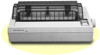
The Interface Boards 2. Carefully place the interface board next to the printer as shown below. Use the CG screw to connect the round end of the FG (frame ground) wire to the main board. 3. Holding the interface board level, rotate it clockwise into position and attach it to the main board. Be sure that the connector pins are properly inserted into the mating connector. A-8 Appendix
-
 1
1 -
2
-
3
-
4
-
5
-
6
-
7
-
8
-
9
-
10
-
11
-
12
-
13
-
14
-
15
-
16
-
17
-
18
-
19
-
20
-
21
-
22
-
23
-
24
-
25
-
26
-
27
-
28
-
29
-
30
-
31
-
32
-
33
-
34
-
35
-
36
-
37
-
38
-
39
-
40
-
41
-
42
-
43
-
44
-
45
-
46
-
47
-
48
-
49
-
50
-
51
-
52
-
53
-
54
-
55
-
56
-
57
-
58
-
59
-
60
-
61
-
62
-
63
-
64
-
65
-
66
-
67
-
68
-
69
-
70
-
71
-
72
-
73
-
74
-
75
-
76
-
77
-
78
-
79
-
80
-
81
-
82
-
83
-
84
-
85
-
86
-
87
-
88
-
89
-
90
-
91
-
92
-
93
-
94
-
95
-
96
-
97
-
98
-
99
-
100
-
101
-
 102
102 -
 103
103 -
 104
104 -
 105
105 -
 106
106 -
 107
107 -
 108
108 -
 109
109 -
 110
110 -
 111
111 -
 112
112 -
113
-
114
-
115
-
116
-
117
-
118
-
119
-
120
-
121
-
122
-
123
-
124
-
125
-
126
-
127
-
128
-
129
-
130
-
131
-
132
-
133
-
134
-
135
-
136
 |
 |

The Interface Boards
2.
Carefully place the interface board
next
to the printer as shown
below. Use
the
CG screw to connect
the
round end of the FG
(frame ground) wire to the main board.
3. Holding the interface board level, rotate it clockwise into
position and
attach
it to
the
main board. Be sure that the
connector pins are properly inserted into the mating connector.
A-8
Appendix