Epson L-1000 User Manual - Page 109
Attaching the upper case, Appendix, the upper and lower cases.
 |
View all Epson L-1000 manuals
Add to My Manuals
Save this manual to your list of manuals |
Page 109 highlights
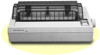
The Interface Boards Attaching the upper case 1. Fit the hinges of the upper case into the openings in the lower case. Now partially lower the upper case. WARNING: Take care not to pinch the FG wire between the upper and lower cases. 2. Carefully insert the control panel cable into the connector labelled CN4 on the main board. A-10 Appendix
-
 1
1 -
2
-
3
-
4
-
5
-
6
-
7
-
8
-
9
-
10
-
11
-
12
-
13
-
14
-
15
-
16
-
17
-
18
-
19
-
20
-
21
-
22
-
23
-
24
-
25
-
26
-
27
-
28
-
29
-
30
-
31
-
32
-
33
-
34
-
35
-
36
-
37
-
38
-
39
-
40
-
41
-
42
-
43
-
44
-
45
-
46
-
47
-
48
-
49
-
50
-
51
-
52
-
53
-
54
-
55
-
56
-
57
-
58
-
59
-
60
-
61
-
62
-
63
-
64
-
65
-
66
-
67
-
68
-
69
-
70
-
71
-
72
-
73
-
74
-
75
-
76
-
77
-
78
-
79
-
80
-
81
-
82
-
83
-
84
-
85
-
86
-
87
-
88
-
89
-
90
-
91
-
92
-
93
-
94
-
95
-
96
-
97
-
98
-
99
-
100
-
101
-
102
-
103
-
 104
104 -
 105
105 -
 106
106 -
 107
107 -
 108
108 -
 109
109 -
 110
110 -
 111
111 -
 112
112 -
 113
113 -
 114
114 -
115
-
116
-
117
-
118
-
119
-
120
-
121
-
122
-
123
-
124
-
125
-
126
-
127
-
128
-
129
-
130
-
131
-
132
-
133
-
134
-
135
-
136
 |
 |

The Interface Boards
Attaching the upper case
1.
Fit
the
hinges of
the
upper case into the openings in the lower
case. Now partially lower the upper case.
WARNING:
Take care not to pinch the FG wire between
the upper and lower cases.
2. Carefully insert
the
control panel cable into the connector
labelled CN4 on the main board.
A-10
Appendix