Fisher and Paykel CDV3-304H-N Installation Guide
Fisher and Paykel CDV3-304H-N Manual
 |
View all Fisher and Paykel CDV3-304H-N manuals
Add to My Manuals
Save this manual to your list of manuals |
Fisher and Paykel CDV3-304H-N manual content summary:
- Fisher and Paykel CDV3-304H-N | Installation Guide - Page 1
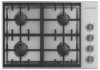
GAS COOKTOPS PROFESSIONAL CDV3-365H, CDV3-365 CDV3-304H, CDV3-304 INSTALLATION GUIDE US CA - Fisher and Paykel CDV3-304H-N | Installation Guide - Page 2
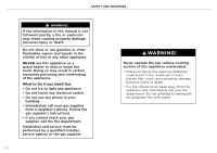
AND WARNINGS ! WARNING! If the information in this manual is not followed exactly, a fire or explosion the gas supplier's instructions. • If you cannot reach your gas supplier, call the fire department. Installation and service must be performed by a qualified installer, service agency or the gas - Fisher and Paykel CDV3-304H-N | Installation Guide - Page 3
safety instructions listed below. Read all the guidance before using the appliance. Servicing z Do not repair or replace any part of the appliance unless specifically recommended in the user guide. All other servicing should be undertaken be a Fisher & Paykel trained and supported service technician - Fisher and Paykel CDV3-304H-N | Installation Guide - Page 4
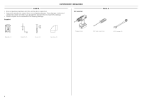
COMPONENTS REQUIRED PARTS z Keep all packing materials until the unit has been inspected. z Inspect the product to ensure there is no shipping damage. If any damage is detected contact the dealer or retailer you bought the product from to report the damage. z Fisher & Paykel is not responsible for - Fisher and Paykel CDV3-304H-N | Installation Guide - Page 5
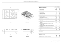
PRODUCT DIMENSIONS 30" MODELS B PRODUCT DIMENSIONS 30" MODELS IN MM A Overall height* 4 5/16 110 m B Overall width 30 762 C Overall depth 21 533 D Height of chassis 4 102 C E Width of chassis 28 7/16 723 F Depth of chassis 19 3/8 492 G Height above countertop 3/8 10 H - Fisher and Paykel CDV3-304H-N | Installation Guide - Page 6
PRODUCT DIMENSIONS 36" MODELS B PRODUCT DIMENSIONS 36" MODELS IN MM A Overall height* 4 5/16 110 m B Overall width 36 915 C Overall depth 21 533 D Height of chassis 4 102 C E Width of chassis 34 7/16 874 F Depth of chassis 19 3/8 492 G Height above countertop 3/8 10 H - Fisher and Paykel CDV3-304H-N | Installation Guide - Page 7
30" CUTOUT D E B A C F CABINETRY DIMENSIONS 36" CUTOUT D E B A C F CABINETRY DIMENSIONS A Min. height allowance* B Depth C Width D Max. depth of overhead cabinetry E Min. width of ventilation hood required F Min. distance from rear edge of cutout to nearest combustible surface top of counter* - Fisher and Paykel CDV3-304H-N | Installation Guide - Page 8
CABINETRY DIMENSIONS CLEARANCES The below clearances apply to both wall and island installations for all models. Ensure the cook surface sits flush or above the adjacent countertop and any openings behind or under the cooktop are sealed. Flow of combustion and ventilation air must not be obstructed - Fisher and Paykel CDV3-304H-N | Installation Guide - Page 9
VENTILATION REQUIREMENTS z Ventilation hoods and blowers are designed for use with single wall ducting, however some local building codes or inspectors may require double wall ducting and/or a damper. Consult local building codes and/or agencies, before installing to ensure local requirements are - Fisher and Paykel CDV3-304H-N | Installation Guide - Page 10
GAS CONNECTION CONSIDERATIONS The following are the available options for connecting the gas line to the cooktop to suit your installation: GAS LINE TO GAS INLET GAS LINE TO ELBOW FACING BACK GAS LINE TO ELBOW FACING SIDE DETAIL DETAIL DETAIL 3 3/8" (85mm) 1 3/4" (44mm) 2 1/2" (64mm) BASE - Fisher and Paykel CDV3-304H-N | Installation Guide - Page 11
120 V 0.10 A 60 Hz z This cooktop must be grounded. z Always disconnect electric supply cord from the wall outlet or service disconnect before servicing this appliance. z Observe all governing codes and ordinances when grounding, in absence of which, observe National Electrical Code ANSI / NFPA - Fisher and Paykel CDV3-304H-N | Installation Guide - Page 12
to provide a maximum pressure of 14" W.C. to the cooktop regulator. A manual shut-off valve (not supplied) must be installed in an accessible location in the shall be conducted according to the manufacturer's instructions. See instructions following. When checking the manifold gas pressure, - Fisher and Paykel CDV3-304H-N | Installation Guide - Page 13
dangerous flame and result in poor burner performance. z If proper operation cannot be obtained, contact Customer Care or your nearest Fisher & Paykel Authorized Service Center. z The rangetop must not be used until proper operation has been achieved. ON z Ensure all dials are set to OFF before - Fisher and Paykel CDV3-304H-N | Installation Guide - Page 14
The pressure regulator which is connected to the manifold is set correctly … Manual gas shut-off valve installed in an accessible location. … Unit tested Receptacle with correctly rated over-current protection is provided for service cord connection. … Adequate ground connection. Complete and keep - Fisher and Paykel CDV3-304H-N | Installation Guide - Page 15
- Fisher and Paykel CDV3-304H-N | Installation Guide - Page 16
may not be available in all markets and are subject to change at any time. The product specifications in this guide apply to the specific products and models described at the date of issue. Under our policy of continuous product improvement, these specifications may change at
-
 1
1 -
 2
2 -
 3
3 -
 4
4 -
 5
5 -
 6
6 -
 7
7 -
8
-
9
-
10
-
11
-
12
-
13
-
14
-
15
-
16
 |
 |

INSTALLATION GUIDE
PROFESSIONAL
CDV3-365H, CDV3-365 CDV3-304H, CDV3-304
GAS COOKTOPS
US CA