Frigidaire CGEF306TPF Installation Instructions - Page 4
B. Drill Pilot Holes and Fasten Bracket, C. Level and position the range, Serial Plate Information
 |
View all Frigidaire CGEF306TPF manuals
Add to My Manuals
Save this manual to your list of manuals |
Page 4 highlights
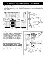
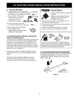
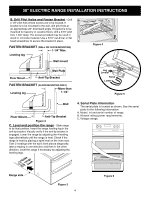
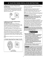
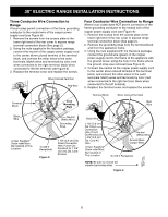
30" ELECTRIC RANGE INSTALLATION INSTRUCTIONS B. Drill Pilot Holes and Fasten Bracket - Drill a 1/8" pilot hole where screws are to be located. If bracket is to be mounted to the wall, drill pilot hole at an approximate 20° downward angle. If bracket is to be mounted to masonry or ceramic floors, drill a 3/16" pilot hole 1-3/4" deep. The screws provided may be used in wood or concrete material. Use a 5/16" nut-driver or flat head screwdriver to secure the bracket in place. FASTEN BRACKET (WALL OR FLOOR MOUNTING) 1-1/4" Max. Leveling leg Wall mount Figure 4 Rear of Range Wall Plate Floor Mount Anti-Tip Bracket FASTEN BRACKET (FLOOR MOUNTING ONLY) More than Leveling leg 1-1/4" Leg Leveler Raise Lower Figure 5 Rear of Range Wall Floor Mount Anti-Tip Bracket Figure 2 C. Level and position the range - Slide range to its final position. Insert the range leveling leg in the anti-tip bracket. Visually verify if the anti-tip bracket is engaged. Lower the range by adjusting the 4 leveling legs alternatively until the range is level. Check if the range is level by placing a spirit level on the oven rack. Take 2 readings with the spirit level placed diagonally; take a reading in one direction and then in the other direction. Level the range if necessary by adjusting the leveling legs. Slidraenbgaeck 4. Serial Plate Information The serial plate is located as shown. See the serial plate for the following information: A. Model, lot and serial number of range. B. Kilowatt rating (power requirements). C. Voltage ratings. Range side Figure 3 4 Figure 6
-
 1
1 -
 2
2 -
 3
3 -
 4
4 -
 5
5 -
 6
6 -
 7
7 -
 8
8 -
 9
9 -
 10
10 -
11
-
12
-
13
-
14
-
15
-
16
-
17
-
18
-
19
-
20
-
21
-
22
-
23
-
24
 |
 |
