Frigidaire CGEF306TPF Installation Instructions - Page 7
Direct Electrical Connection to the, Circuit Breaker, Fuse Box or Junction Box, Checking Operation
 |
View all Frigidaire CGEF306TPF manuals
Add to My Manuals
Save this manual to your list of manuals |
Page 7 highlights
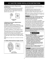
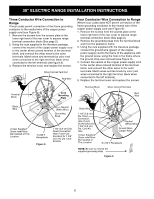
30" ELECTRIC RANGE INSTALLATION INSTRUCTIONS 6.2 Direct Electrical Connection to the Circuit Breaker, Fuse Box or Junction Box If the appliance is connected directly to the circuit breaker, fuse box or junction box, use flexible, armored or nonmetallic sheathed copper cable (with grounding wire). Supply a U.L. listed strain-relief at each end of the cable. At the appliance end, the cable goes through the Direct Connection Hole (see Figure 9) on the Cord Mounting Plate. Wire sizes (copper wire only) and connections must conform to the rating of the appliance. Where local codes permit connecting the appliance-grounding conductor to the neutral (white) wire (see Figure 10): 1. Be sure that no power is supplied on the cable from residence. 2. Follow instructions on previous page for Four Conductor Wire Connection to Range (Fig. 9). 3. In the circuit breaker, fuse box or junction box (Fig. 10): a) Connect the green (or bare copper) wire, the white appliance cable wire, and the neutral (white) wire together. b) Connect the 2 black wires together. c) Connect the 2 red wires together. Neutral (white) Wire Red Wires Cable from Residence Black Wires Junction Box White Wire Green (or Bare Copper) Wire Cable from Appliance U.L.-listed Conduit Connector (or CSA listed) NOTE: Be sure to remove the supplied grounding strap. Figure 10 3-Wire (Grounded Neutral) Electrical System (Example: Junction Box) Where local codes DO NOT permit connecting the appliance-grounding conductor to the neutral (white) wire, or if connecting to 4-wire electrical system (see Figure 11): 1. Be sure that no power is supplied on the cable from residence. 2. Follow instructions on previous page for Four Conductor Wire Connection to Range (Fig. 9). 3. In the circuit breaker, fuse box or junction box (Fig. 11): a) Connect the white appliance cable wire to the neutral (white) wire. b) Connect the 2 black wires together. c) Connect the 2 red wires together. d) Connect the green (or bare copper) grounding wire to the grounding wire of the circuit breaker, fuse box or junction box. Green (or Bare Copper) Wire Cable from Residence Red Wires White Wire Green (or Bare Copper) Wire Junction Box Black Wires Cable from Appliance White Wire U.L.-listed Conduit Connector (or CSA listed) NOTE: Be sure to remove the supplied grounding strap. Figure 11 - 4-Wire Electrical System (Example: Junction Box) 7. Checking Operation Refer to the Use and Care Guide for operation. CAUTION Do not touch cooktop glass or elements. They may be hot enough to burn you. Before You Call for Service Read the Before You Call for Service Checklist and operating instructions in your Use and Care Guide. It may save you time and expense. The list includes common occurrences that are not the result of defective workmanship or materials in this appliance. 7
-
 1
1 -
 2
2 -
 3
3 -
 4
4 -
 5
5 -
 6
6 -
 7
7 -
 8
8 -
 9
9 -
 10
10 -
 11
11 -
 12
12 -
13
-
14
-
15
-
16
-
17
-
18
-
19
-
20
-
21
-
22
-
23
-
24
 |
 |
