Garmin Cortex VHF and AIS Cortex Handset Installation Guide - Page 6
To install a Bulkhead Connector, H1 Bulkhead Connector
 |
View all Garmin Cortex VHF and AIS manuals
Add to My Manuals
Save this manual to your list of manuals |
Page 6 highlights
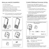
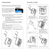
H1 Bulkhead Connector FRONT ON ANGLE AS CRADLE ABOVE To install a Bulkhead Connector The Bulkhead Connector can be mounted almost anywhere where a WiFi connection to the M1 hub can be achieved. Consider the following position and power connection requirements when choosing a Bulkhead Connector CTRAASDSELEMloABcBLYOa-- Vt(TPiE1oho1F2n1FeR.sV:BR.OiAtBBONioSoAuTNErnSl,OTk2SENthO,4OheSACVeNOKNaEGBDdACTLuKNC&EClEGAk)NoT.ShLUn&ECeTnRaAANeAdSScDUStELCCToEMRroAABAniSBLFs1DYnORS.OweELVBNEAEMcirSTtAeBEoO,BdLrSNYOOntACoVeNKEaGpErTLoE&twAhNSeeUCrTHRAA1SDSLcEEMrAaBBdLOYleVE. - The spiral tether cable of the H1 stretches to a maximum length of approximately 2M (6ft). HINT - The Bulkhead Connector base is supplied preassembled and can be rotated in 90 degree increments prior to fastening to achieve a convenient installation angle once the H1 plug is inserted. Arrows on the Mounting Base indicate the correct vertical NUT ASoSrEieMnBtaLYtion for most S CRAiDnLsEtaAllBaOtioVnEs. Mounting Power cable 1. Us1e. BthAeSME,oSuOntCinKgEBTa&seNUasTaA S SEMBLY temFRpOlaNteTfoOrNmAaNrkGinLgEthAeS CRADLE ABOVE position of mounting holes and 2. Mark the holes required and the power cable hole. 1d. rBilAl SthEe, mSO. CKET & NUT ASSEMBLY FRONT ON ANGLE AS CRADLE ABOVE Mounting ring 3. If required (eg, exterior 3a. Pass the mounting ring of the installations) add the Waterproof Waterproof Cap through the Cap in steps 3a and 3b. keyhole slot of the Cover. CAUTION - Ensure tha1.tBtAhSeE, mSOiCnKimETu&mNUsTaAfeSSEcMoBmLYpass distance is maintainedF.RSONtaTnOdNaArNdG: L0E.A8SmC,RASDteLEeAriBnOgV:E0.4m. Mounting Base Cover 1. BASE, SOCKET & NUT ASSEMBLY FRONT ON ANGLE AS CRADLE ABOVE Waterproof Cap (IP67) 10 Power cable 4. Pass the power cable of the 3b. Slide the mounting ring (with Mounting Base through the Cap attached) over the thread of power cable hole. (Optional the Mounting Base. Waterproof Cap not shown) 5. Add marine sealant to waterproof the holes if mounting externally. Secure with fastenings of your choice. (Optional Waterproof Cap not 6. Snap the Cover onto the shown) Mounting Base. 11
-
 1
1 -
 2
2 -
 3
3 -
 4
4 -
 5
5 -
 6
6 -
 7
7 -
 8
8 -
 9
9 -
 10
10 -
 11
11 -
 12
12 -
13
 |
 |
