Garmin GDL 59 – Data Logger & Wi-Fi Datalink Installation Manual
Garmin GDL 59 – Data Logger & Wi-Fi Datalink Manual
 |
View all Garmin GDL 59 – Data Logger & Wi-Fi Datalink manuals
Add to My Manuals
Save this manual to your list of manuals |
Garmin GDL 59 – Data Logger & Wi-Fi Datalink manual content summary:
- Garmin GDL 59 – Data Logger & Wi-Fi Datalink | Installation Manual - Page 1
GDL 59 Data Link Installation Manual 190-00837-00 August, 2010 Revision C - Garmin GDL 59 – Data Logger & Wi-Fi Datalink | Installation Manual - Page 2
C 08/17/10 Added Flight Data Services activation information Page A Revision C DOCUMENT PAGINATION Section Table of Contents Section 1 Section 2 Section 3 Section 4 Appendix A Appendix B Page Range i-iv 1-1-1-8 2-1-2-2 3-1-3-6 4-1-4-6 A-1-A-8 B-1-B-2 GDL 59 Installation Manual 190-00837-00 - Garmin GDL 59 – Data Logger & Wi-Fi Datalink | Installation Manual - Page 3
/perchlorate. CURRENT REVISION DESCRIPTION Revision C Page Number(s) 1-5 1-7 3-6 Section Number 1.4.5 1.5.3 3.8 Description of Change Added new Wi-Fi info Added 802.11 info to Table 1-9 Added Flight Data Services activation info GDL 59 Installation Manual 190-00837-00 Page i Revision C - Garmin GDL 59 – Data Logger & Wi-Fi Datalink | Installation Manual - Page 4
Installation ...3-1 3.3 Wi-Fi Antenna Installation ...3-2 3.4 Coaxial Cable Installation...3-4 3.5 Backshell Assembly and Installation 3-5 3.6 Final Installation ...3-5 3.7 Post Installation Configuration and Checkout 3-6 3.8 Activation of Garmin Flight Data Services 3-6 3.9 Continued - Garmin GDL 59 – Data Logger & Wi-Fi Datalink | Installation Manual - Page 5
59 Stand-alone Rack Outline Drawing (Sheet 2 A-7 B-1 GDL 59 Example Interconnect ...B-1 TABLE LIST OF TABLES PAGE 1-1 Unit with Modular Rack ...1-3 1-2 Unit with Stand-alone Rack...1-4 1-3 Input Voltage ...1-4 1-4 Maximum Current Specifications ...1-4 1-5 General Specifications ...1-4 1-6 Wi-Fi - Garmin GDL 59 – Data Logger & Wi-Fi Datalink | Installation Manual - Page 6
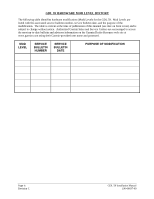
for the GDL 59. Mod Levels are listed with the associated service bulletin number, service bulletin date, and the purpose of the modification. The table is current at the time of publication of this manual (see date on front cover) and is subject to change without notice. Authorized Garmin Sales and - Garmin GDL 59 – Data Logger & Wi-Fi Datalink | Installation Manual - Page 7
and ground computers while the aircraft is on the ground using the IEEE 802.11g ("Wi-Fi") protocol. The GDL 59 also provides two interfaces to an optional GSR 56, which adds airborne low speed data link and voice communication capability. GDL 59 Installation Manual 190-00837-00 Page 1-1 Revision C - Garmin GDL 59 – Data Logger & Wi-Fi Datalink | Installation Manual - Page 8
(or GDL 69A or GSD 41) HSDB Other Avionics HSDB WiFi RS-232 Iridium Audio GSR 56 (Optional) GDL 59 RS-232 Iridium Audio GSR 56 (Optional) Iridiu m Iridiu m POTS Audio Audio Panel(s) Hand set Figure 1-2. GDL 59 Block Diagram Page 1-2 Revision C GDL 59 Installation Manual 190-00837 - Garmin GDL 59 – Data Logger & Wi-Fi Datalink | Installation Manual - Page 9
To simplify operation of the telephone, Garmin recommends using a POTS telephone that does not have a Hold button. • RS-232 I/O: The GDL 59 has two RS-232 ports. RS-232 is the primary communication path between the GDL 59 and the GSR 56 units. • Ethernet Ports: The GDL 59 provides three 10/100 Base - Garmin GDL 59 – Data Logger & Wi-Fi Datalink | Installation Manual - Page 10
A On 0.572 A *DATA LINK REMOTE PWR OFF in active state Max Current @ 14 Vdc 0.100 A 1.15 A NOTE The GDL 59 is not certified for use Temperature Range Humidity Altitude Range Software Compliance Maximum Average Power Input from Page 1-4 Revision C GDL 59 Installation Manual 190-00837-00 - Garmin GDL 59 – Data Logger & Wi-Fi Datalink | Installation Manual - Page 11
agreement, are not supported for data transfer from the GDL 59 • The access point must be capable of receiving at a rate of 18 Mbps • The Wi-Fi network shall be compatible with WEP64, WEP128,WPA-PSK, or WPA2-PSK encryption formats, and with all of those formats associated encryption combinations and - Garmin GDL 59 – Data Logger & Wi-Fi Datalink | Installation Manual - Page 12
subpart 7a which requires furnishing each person receiving a GDL 59 copy of the data listed in paragraph 5l of TSO-C139. 4. Garmin was granted a deviation from TSO-C139 subpart 7b which requires furnishing each person receiving a GDL 59 a copy of the data in paragraphs 5l, 5m, and 5n of TSO-C139 - Garmin GDL 59 – Data Logger & Wi-Fi Datalink | Installation Manual - Page 13
802.11 Radio Data Link Data Link Radio Controller Data Link Radio Controller Flight Data Logger Table 1-9. Non-TSO Functions Design Assurance RTCA/DO-178B Level E RTCA/DO-178B Level D RTCA/DO-178B Level E RTCA/DO-178B Level D RTCA/DO-178B Level D Applicable LRU Software Part Numbers 006-B0736 - Garmin GDL 59 – Data Logger & Wi-Fi Datalink | Installation Manual - Page 14
151st Street Olathe, Kansas 66062, U.S.A. Phone: 913/397.8200 FAX: 913/397.0836 Garmin (Europe) Ltd. Liberty House, Bulls Copse Road Hounsdown Business Park Romsey, SO40 9RB, U.K. Phone: +44/ (0) 870.8501241 FAX: +44/ (0) 870.8501251 Page 1-8 Revision C GDL 59 Installation Manual 190-00837-00 - Garmin GDL 59 – Data Logger & Wi-Fi Datalink | Installation Manual - Page 15
retro-fit installations that comply with FAA regulations. Refer to the G1000 System Installation Manual, Garmin part number 190-00303-00 for further details on the mechanical aspects. 2.2 Installation Materials The GDL 59 is available only as a single unit under the following part number: Table - Garmin GDL 59 – Data Logger & Wi-Fi Datalink | Installation Manual - Page 16
is needed for the GDL 59. 2.6 Mounting Requirements The GDL 59 mounting surface should be from High-Intensity Radiation Fields (HIRF). The GDL 59 can be mounted using the G1000 main system in Section 2.3. Refer to the Figure A-1 GDL 59 Modular Rack Outline Drawing for nutplate placement locations. - Garmin GDL 59 – Data Logger & Wi-Fi Datalink | Installation Manual - Page 17
and all packing materials. Do not return the unit to Garmin until the carrier has authorized the claim. Retain the original input and output signals. Required connectors and associated hardware are supplied with the connector kit ( GDL 59 Installation Manual 190-00837-00 Page 3-1 Revision C - Garmin GDL 59 – Data Logger & Wi-Fi Datalink | Installation Manual - Page 18
by this manual. There are several critical factors to take into consideration before installing an antenna for the GDL 59, these factors are addressed in the following sections. 3.3.1 Antenna Mounting For installation mounting of the Wi-Fi antenna, follow the manufacturer's instructions and the - Garmin GDL 59 – Data Logger & Wi-Fi Datalink | Installation Manual - Page 19
gain is 5 dB. (2) Wi-Fi antenna must be omni-directional. (3) The interconnect and antenna gain/loss component must be between +6dB and -4dB. If the interconnect and antenna gain/loss component is outside this range, additional gain or loss must be added between the antenna and the GDL 59 RF input - Garmin GDL 59 – Data Logger & Wi-Fi Datalink | Installation Manual - Page 20
the desired length and install TNC connectors at each end per the cabling instructions listed in Figure 3-1. For routing convenience, one end of the coaxial run can be terminated prior to installation. 3. With the GDL 59 receiver and antenna installed, route and clamp the coaxial cable in position - Garmin GDL 59 – Data Logger & Wi-Fi Datalink | Installation Manual - Page 21
Assembly and Installation The GDL 59 connector kit includes a Garmin backshell assembly. Garmin's backshell also gives the installer the ability to easily terminate shield grounds at the backshell housing using the Shield Block method. To assemble the backshell refer to instructions provided in the - Garmin GDL 59 – Data Logger & Wi-Fi Datalink | Installation Manual - Page 22
Manual, Garmin part number 190-00303-04. For actual aircraft installation/checkout, use only aircraft manufacturer approved checkout procedures. 3.8 Activation of Garmin Flight Data Services In order to activate the GDL 59 for Garmin Flight Data Services, please contact Garmin Product Support - Garmin GDL 59 – Data Logger & Wi-Fi Datalink | Installation Manual - Page 23
78 40 41 42 43 44 45 46 47 48 49 50 51 52 53 54 55 56 57 58 59 21 22 23 24 25 26 27 28 29 30 31 32 33 34 35 36 37 38 39 AUDIO OUT LO 38 AUDIO SYSTEM 1 AUDIO IN LO * Denotes Active Low (Ground to activate) GDL 59 Installation Manual 190-00837-00 I/O Out In Out In Out In Out In Out In --In Out In - Garmin GDL 59 – Data Logger & Wi-Fi Datalink | Installation Manual - Page 24
1 In 73 IRIDIUM 1 REMOTE POWER ON* Out 74 IRIDIUM 2 REMOTE POWER ON* Out 75 DATA LINK REMOTE POWER OFF In 76 IRIDIUM 2 STATUS DISCRETE* IN In 77 RESERVED -- 78 POTS HANDSET TIP I/O * Denotes Active Low (Ground to activate) Page 4-2 Revision C GDL 59 Installation Manual 190-00837-00 - Garmin GDL 59 – Data Logger & Wi-Fi Datalink | Installation Manual - Page 25
(active) Pin Name DATA LINK REMOTE POWER OFF Connector Pin I/O P591 75 In 4.3 Installation Selection Pins 4.3.1 Iridium Status Inputs Pin Name IRIDIUM 1 STATUS DISCRETE* IN IRIDIUM 2 STATUS DISCRETE* IN Connector Pin I/O P591 56 In P591 76 In GDL 59 Installation Manual 190-00837-00 - Garmin GDL 59 – Data Logger & Wi-Fi Datalink | Installation Manual - Page 26
GDL 59 has two Ethernet based high speed data busses (HSDB) that are used to interface with other LRUs in the Garmin Integrated Flight Deck system. These busses meet the hardware aspects of IEEE standard 802.3 for 10/100 Base T Ethernet communications C GDL 59 Installation Manual 190-00837-00 - Garmin GDL 59 – Data Logger & Wi-Fi Datalink | Installation Manual - Page 27
4.4.2 User Ethernet The GDL 59 has three Ethernet data busses that meet the hardware aspects of IEEE standard 802.3 for 10/100 Base T Ethernet communications. NOTE Garmin recommends leaving USER ETHERNET 3 unconnected, as it may be used for other functions in the future. Pin Name USER ETHERNET IN 3 - Garmin GDL 59 – Data Logger & Wi-Fi Datalink | Installation Manual - Page 28
4.4.4 Handset POTS (Plain Old Telephone Service) Input/Output The POTS interface shall: 1) Be capable of detecting a hook-switch flash signal where the on- to connect AUDIO SYTEM 2 AUDIO OUT (pins 18 and 37) to a differential input only. Page 4-6 Revision C GDL 59 Installation Manual 190-00837-00 - Garmin GDL 59 – Data Logger & Wi-Fi Datalink | Installation Manual - Page 29
TYP 7.26 184.4 6.300 160.02 3.0 76 .36 9.1 TYP .480 12.19 TYP 4X NOTE 3 .480 12.19 .480 12.19 TYP .360 9.14 TYP GDL 59 Installation Manual 190-00837-00 4.3 109 4X NOTE 3 9.07 230.4 .377 9.58 TYP 3.727 94.67 TYP ANTENNA J591 NOTES: 1. DIMENSIONS: INCHES[mm] 2. DIMENSIONS ARE SHOWN - Garmin GDL 59 – Data Logger & Wi-Fi Datalink | Installation Manual - Page 30
DRAWINGS PART OF NUTPLATE KIT 011-00915-00 8 PLCS GDL 59 011-01746-00 GDL 59 Installation Manual 190-00837-00 MODULAR RACK 115-00411-00 BACK PLATE KIT 011-00796-02 PART OF CONNECTOR KIT 011-01760-00 2 PLCS NUTPLATE KIT 011-00915-00 (PREFERRED WITH GARMIN SYSTEM RACK) OR 011-01148-00 (NOT SHOWN - Garmin GDL 59 – Data Logger & Wi-Fi Datalink | Installation Manual - Page 31
J591 2X 1.63 41.3 2X 4.500 114.30 2X 6.914 175.62 3X 6.426 163.22 2X 1.60 40.5 2X .37 9.4 2X .728 18.49 GDL 59 Installation Manual 190-00837-00 8.710 221.23 9.13 231.9 2X 4.458 113.22 4X NOTE 4 NOTES: 1. DIMENSIONS: INCHES[mm] 2. DIMENSIONS ARE SHOWN FOR REFERENCE ONLY - Garmin GDL 59 – Data Logger & Wi-Fi Datalink | Installation Manual - Page 32
AND INSTALLATION DRAWINGS STANDALONE INSTALLATION GDL 59 Installation Manual 190-00837-00 GDL 59 011-01746-00 STANDALONE RACK 115-00658-00 BACK PLATE KIT 011-00796-02 PART OF CONNECTOR KIT 011-01760-00 2 PLCS CONNECTOR KIT 011-01760-00 Figure A-2. GDL 59 Stand-alone Rack Outline Drawing - Garmin GDL 59 – Data Logger & Wi-Fi Datalink | Installation Manual - Page 33
8 GDL 59 Installation Manual 190-00837-00 GDL 59 DATALINK P591 SIGNAL GROUND 44 BLU RS 232 IN 1 64 ORN P592 WI-FI ANTENNA WHT BLU S WHT BLU 1P3471 GMA 1347 AUDIO PANEL TEL AUDIO IN LO 1A TIP RING P691 32 33 30 31 S GDL 69A DATA LINK ETHERNET OUT 3 B ETHERNET OUT 3 A ETHERNET IN 3 B
-
 1
1 -
 2
2 -
 3
3 -
 4
4 -
 5
5 -
 6
6 -
 7
7 -
8
-
9
-
10
-
11
-
12
-
13
-
14
-
15
-
16
-
17
-
18
-
19
-
20
-
21
-
22
-
23
-
24
-
25
-
26
-
27
-
28
-
29
-
30
-
31
-
32
-
33
 |
 |

190-00837-00
August, 2010
Revision C
GDL 59
Data Link
Installation Manual