GDL 59 Installation Manual
Page iii
190-00837-00
Revision C
LIST OF ILLUSTRATIONS
FIGURE
PAGE
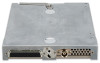
1-1 GDL 59 Unit View
............................................................................................................................
1-1
1-2 GDL 59 Block Diagram
.....................................................................................................................
1-2
2-1 GDL 59 Modular Unit Rack
..............................................................................................................
2-2
3-1 TNC Connector Installation
...............................................................................................................
3-4
A-1 GDL 59 Modular Rack Outline Drawing (Sheet 1 of 2)
...................................................................
A-1
A-1 GDL 59 Modular Rack Outline Drawing (Sheet 2)
..........................................................................
A-3
A-2 GDL 59 Stand-alone Rack Outline Drawing (Sheet 1 of 2)
.............................................................
A-5
A-2 GDL 59 Stand-alone Rack Outline Drawing (Sheet 2)
....................................................................
A-7
B-1 GDL 59 Example Interconnect
.........................................................................................................
B-1
LIST OF TABLES
TABLE
PAGE
1-1 Unit with Modular Rack
....................................................................................................................
1-3
1-2 Unit with Stand-alone Rack
...............................................................................................................
1-4
1-3 Input Voltage
.....................................................................................................................................
1-4
1-4 Maximum Current Specifications
......................................................................................................
1-4
1-5 General Specifications
.......................................................................................................................
1-4
1-6 Wi-Fi Antenna Minimum Requirements
...........................................................................................
1-5
1-7 TSO/ETSO Authorizations
................................................................................................................
1-6
1-8 TSO/ETSO Deviations
......................................................................................................................
1-6
1-9 Non-TSO Functions
...........................................................................................................................
1-7
1-10 Referenced Publications
....................................................................................................................
1-7
2-1 Unit Part Number
...............................................................................................................................
2-1
2-2 Accessories
........................................................................................................................................
2-1
3-1 Pin Contact Part Numbers
..................................................................................................................
3-1
3-2 Recommended Crimp Tools
..............................................................................................................
3-1
 1
1 2
2 3
3 4
4 5
5 6
6 7
7 8
8 9
9 10
10 11
11

