Garmin GMR xHD3 Radar Installation Instructions
Garmin GMR xHD3 Radar Manual
 |
View all Garmin GMR xHD3 Radar manuals
Add to My Manuals
Save this manual to your list of manuals |
Garmin GMR xHD3 Radar manual content summary:
- Garmin GMR xHD3 Radar | Installation Instructions - Page 1
a Garmin® authorized service technician. Any damage resulting from opening the unit by anyone other than a Garmin authorized service technician will not be device. For instructions on updating the software, see your chartplotter owner's manual at support.garmin.com. June 2023 GUID-EB209D1E-8C29- - Garmin GMR xHD3 Radar | Installation Instructions - Page 2
Tools Needed • #2 Phillips screwdriver • 5 mm hex wrench • Drill and 15.0 mm (19/32 in.) drill bit • 17 mm (21/32 in.) wrench and torque wrench • A length of 3.31 mm² (12 AWG) copper wire to ground the radar housing (and voltage converter, if applicable). • Marine sealant 2 - Garmin GMR xHD3 Radar | Installation Instructions - Page 3
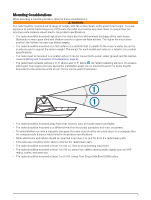
targets. • The radar should be mounted on a flat surface or a platform that is parallel to the vessel's water line and is sturdy enough to support the radar's weight. The weight for each model and antenna is listed in the product specifications. • The radar must be mounted in a location where it - Garmin GMR xHD3 Radar | Installation Instructions - Page 4
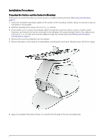
Installation Procedures Preparing the Surface and the Radar for Mounting Before you can mount the radar, you must choose a suitable mounting location (Mounting Considerations, page 3). 1 Secure the included mounting template to the surface at the mounting location, along the bow-stern axis, as - Garmin GMR xHD3 Radar | Installation Instructions - Page 5
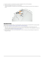
7 Insert the ends of the threaded rods coated in Petrolatum Primer into the pedestal. 8 Tighten the threaded rods using a 5 mm hex wrench. To avoid damaging the pedestal, you should stop tightening the threaded rods when they no longer turn easily. Mounting the Radar Before you can mount the radar, - Garmin GMR xHD3 Radar | Installation Instructions - Page 6
3 From under the mounting surface, place the shoulder washers on the threaded rods and feed them into the mounting surface so they fit securely. 4 Place the flat washers , lock washers , and hex nuts on the threaded rods. 5 Torque the hex nuts to 1.5 kgf-m (130 lbf-in. [11 lbf-ft.]) to securely - Garmin GMR xHD3 Radar | Installation Instructions - Page 7
Installing the Antenna Before you can install the antenna on the pedestal, you must securely mount the pedestal (Mounting the Radar, page 5). 1 Remove the protective cover from the waveguide on the top of the pedestal. 2 Remove the mounting hardware from the bottom of the antenna . These screws and - Garmin GMR xHD3 Radar | Installation Instructions - Page 8
4 Secure the antenna to the pedestal using the hex screws , spring washers , and flat washers you removed from the antenna in step 2. 5 Using a torque wrench, tighten the hex screws to 0.81 kgf-m (70 lfb-in. [6 lbf-ft.]) to fasten the antenna to the pedestal without damaging the antenna or the - Garmin GMR xHD3 Radar | Installation Instructions - Page 9
Connecting to Power Through the Voltage Converter WARNING When connecting the power cable, do not remove the in-line fuse holder. To prevent the possibility of injury or product damage caused by fire or overheating, the appropriate fuse must be in place as indicated in the product specifications. - Garmin GMR xHD3 Radar | Installation Instructions - Page 10
Item Description To the Garmin network 15 A fuse holder Red (+) Black (-) To the boat battery (10 to 32 Vdc) 30 A fuse holder Water ground connection 1 Route the power cable to the radar and the voltage converter. 2 Use crimp connectors and heat-shrink tubing to connect the power cable to - Garmin GMR xHD3 Radar | Installation Instructions - Page 11
Item Description To the Garmin network 15 A fuse holder To the boat battery (11 to 32 Vdc) Water ground connection 1 Route the power cable to the radar and boat battery. 2 Connect the power cable to the boat battery. 3 Connect the power cable to the POWER port on the radar. Power Cable - Garmin GMR xHD3 Radar | Installation Instructions - Page 12
Grounding the Radar The radar (and voltage converter, if applicable) must be connected to the appropriate type of ground using a 3.31 mm² (12 AWG) copper wire (not included). 1 Route a 3.31 mm² (12 AWG) copper wire to a water ground location and to the radar pedestal. 2 Connect the wire to the - Garmin GMR xHD3 Radar | Installation Instructions - Page 13
of this radar are controlled with your Garmin chartplotter. See the Radar section of your chartplotter's owner's manual for operating instructions. To download the latest manual, go to garmin.com /manuals. If you have more than one radar on your boat, you must be viewing the radar screen for - Garmin GMR xHD3 Radar | Installation Instructions - Page 14
Measuring and Setting the Front-of-Boat Offset The front-of-boat offset compensates for the physical orientation of the radar scanner on a boat, if the radar scanner does not align with the bow-stern axis. The front-of-boat offset setting configured for use in one radar mode is applied to every - Garmin GMR xHD3 Radar | Installation Instructions - Page 15
Specifications Specification Pedestal weight Antenna weight Power cable length Network cable length Antenna rotation speed Maximum wind load Temperature range Humidity Water rating Max. range Min. range Peak transmit power Beam width Bearing accuracy Input voltage Fuse Power consumption, standby - Garmin GMR xHD3 Radar | Installation Instructions - Page 16
Antenna Specifications Specification Type Horizontal beam width Horizontal side lobes Vertical beam width Antenna gain Polarization Measurement End-fed slotted waveguide 4 ft. antenna: 1.8 degrees 6 ft. antenna: 1.1 degrees -23 dB within ±10 degrees of main -30 dB outside ±10 degrees of main 23º 4 - Garmin GMR xHD3 Radar | Installation Instructions - Page 17
Dimensions Item Measurement 181.8 mm (7 3/16 in.) 236.2 mm (9 5/16 in.) 25 mm (1 in.) 125 mm (4 15/16 in.) 50 mm (1 15/16 in.) 150 mm (5 29/32 in.) 140 mm (5 1/2 in.) 200 mm (7 7/8 in.) Description Center of rotation to the rear of the pedestal. Center of rotation to the front of the pedestal. - Garmin GMR xHD3 Radar | Installation Instructions - Page 18
Item Measurement 4 ft. models: 132.7 cm (4 ft. 4 1/4 in.) 6 ft. models: 193.7 cm (6 ft. 4 1/4 in.) 45.1 cm (17 3/4 in.) 31.8 cm (12 1/2 in.) Description Antenna length. Base of the pedestal to the top of the antenna. Width of the pedestal. Open-Source Software License To view the open-source - Garmin GMR xHD3 Radar | Installation Instructions - Page 19
Extensions section of these instructions to make sure the can help troubleshoot installation problems. Status support for assis tance. Contacting Garmin Support • Go to support.garmin.com for help and information, such as product manuals, frequently asked questions, videos, and customer support - Garmin GMR xHD3 Radar | Installation Instructions - Page 20
© 2023 Garmin Ltd. or its subsidiaries support.garmin.com
-
 1
1 -
 2
2 -
 3
3 -
 4
4 -
 5
5 -
 6
6 -
 7
7 -
8
-
9
-
10
-
11
-
12
-
13
-
14
-
15
-
16
-
17
-
18
-
19
-
20
 |
 |

GMR
™
430/1230/2530
XHD3
SERIES
INSTALLATION
INSTRUCTIONS
Important Safety Information
WARNING
See the
Important Safety and Product Information
guide in the product box for product warnings and other
important information.
Failure to install this device according to these instructions could result in personal injury, damage to the vessel
or device, or poor product performance.
The radar transmits electromagnetic energy. To avoid possible personal injury, damage to the vessel or device,
or poor product performance, ensure that the radar is installed according to the recommendations in these
instructions and that all personnel are clear of the path of the radar beam before transmitting. When properly
installed and operated, the use of this radar conforms to the requirements of ANSI/IEEE C95.1-1992 Standard
for Safety Levels with Respect to Human Exposure to Radio Frequency Electromagnetic Fields.
To avoid possible personal injury, do not look directly at the antenna at close range when the radar is
transmitting. Eyes are the most sensitive part of the body to electromagnetic energy.
When connecting the power cable, do not remove the in-line fuse holder. To prevent the possibility of injury or
product damage caused by fire or overheating, the appropriate fuse must be in place as indicated in the product
specifications. Connecting the power cable without the appropriate fuse in place voids the product warranty.
CAUTION
For the best possible performance and to avoid potential injury, damage to the device, or damage to your vessel,
installation by a qualified marine installer is recommended.
Opening the device may result in personal injury and/or damage to the device. This device contains no user-
serviceable parts, and should be opened only by a Garmin
®
authorized service technician. Any damage resulting
from opening the unit by anyone other than a Garmin authorized service technician will not be covered by the
Garmin warranty.
This device should be used only as a navigational aid. Using the device for any purpose requiring precise
measurement or direction, distance, location, or topography may result in personal injury or damage to the
vessel.
To avoid possible personal injury, always wear safety goggles, ear protection, and a dust mask when drilling,
cutting, or sanding.
NOTICE
When drilling or cutting, always check what is on the opposite side of the surface to avoid damaging the vessel.
Software
Update
You must update the Garmin chartplotter software when you install this device. For instructions on updating the
software, see your chartplotter owner's manual at
support.garmin.com
.
GUID-EB209D1E-8C29-450E-B406-01E29CD7AD9A v2
June 2023