GE 60-774 Installation Instructions
GE 60-774 - Security SuperBus 2000 8-Zone Input Module Manual
 |
UPC - 046188091768
View all GE 60-774 manuals
Add to My Manuals
Save this manual to your list of manuals |
GE 60-774 manual content summary:
- GE 60-774 | Installation Instructions - Page 1
there is an open/short circuit. Advent® panels can support multiple modules for up to 250 zone inputs. UltraGard® panels can support up to eight modules for 64 additional zone inputs. Concord™ panels can be expanded up to 76 zone inputs. For additional security, the plastic case includes space for - GE 60-774 | Installation Instructions - Page 2
that require it (see specific panel Installation Instructions). R Maximum current draw of each SuperBus 2000 8Z Input Module is 35 mA. R Do not exceed the maximum wire length from the panel to the module (see Table 3). Table 3: Maximum Wire Lengths Panel Maximum Wire Length Advent 22 ga. 1,800 - GE 60-774 | Installation Instructions - Page 3
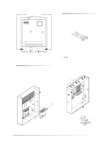
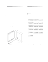
if a receiver module is not being used, the mounting clips may be used for the 8 Zone Input Module. 5. Push the lower-right corner of the module onto the support standoff (see detail in Figure 6). 6. Gently press the module up and onto the cabinet side tab. USABLE MOUNTING CLIPS (6) PANEL CABINET - GE 60-774 | Installation Instructions - Page 4
(RED) ZONE 8 ZONE COMMON ZONE 7 ZONE 6 ZONE COMMON ZONE 5 ZONE 4 ZONE COMMON ZONE 3 ZONE 2 ZONE COMMON ZONE 1 1 2 3 4 5 6 7 8 9 10 11 12 13 14 15 16 TO PANEL TO ZONE SUPERBUS TERMINALS INPUT OR CONNECTOR DEVICE (SEE TABLE) (SHARED COMMONS) 9712G03A.DSF Figure 7. General Module Wiring Table - GE 60-774 | Installation Instructions - Page 5
wire the switch to one of the module zone input terminals or unused panel zone input terminals. Once programmed, if someone opens the module cover, the tamper switch opens and causes an alarm 234567 8 1 234567 8 UNIT NUMBER 9 UNIT NUMBER 10 UNIT NUMBER 11 M ON M ON M ON A A A 1 234567 8 1 - GE 60-774 | Installation Instructions - Page 6
Troubleshooting." Existing Installations Concord Panels- Same as new installation. Advent Panels- 1. Verify that all wiring between the panel and module is correct. 2. Connect the panel backup battery(s) and restore panel AC power. Alphanumeric touchpad displays should come on. 3. Press 8 for System - GE 60-774 | Installation Instructions - Page 7
or Concord system uses hardwire sensors only, turn off the Receiver Failure feature in the panel. Refer to the panel Installation Instructions for details. Troubleshooting Table 6 describes what to do if the module does not work correctly. Table 6. Troubleshooting Problem The green POWER - GE 60-774 | Installation Instructions - Page 8
instruction manual, panel receiver to separate outlets, R on different branch circuits. Consult the dealer or an experienced radio/TV technician for help. 2266 Second Street North North Saint Paul, MN 55109-2900 T: 651/777-2690 F: 651/779-4890 1-800-777-1415 www.itii.com ©2000 Interlogix™, Inc. ITI
-
 1
1 -
 2
2 -
 3
3 -
 4
4 -
 5
5 -
 6
6 -
 7
7 -
8
 |
 |
1
6XSHU%XV
±
²³´´´
µ=²,QSXW²0RGXOH
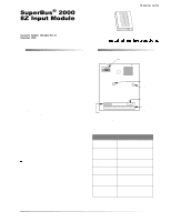
ITI Part No. 60-774
Document Number: 466-1606 Rev. B
November 2000
Product Summary
Each SuperBus
®
2000 8-Zone Input Module adds eight
supervised hardwire zones. Each module includes mounting
hardware and eight 2.0K ohm end-of-line (EOL) resistors.
Power for the module is provided by the panel.
Both normally open and normally closed detectors can be
wired to module inputs. Using an EOL resistor on each loop
input, the module monitors all zones and alerts the panel if
there is an open/short circuit.
Advent
®
panels can support multiple modules for up to 250
zone inputs. UltraGard
®
panels can support up to eight
modules for 64 additional zone inputs. Concord
™
panels can
be expanded up to 76 zone inputs.
For additional security, the plastic case includes space for
installing a magnet and reed switch that can provide tamper
protection to detect cover removal.
SuperBus 2000
vs.
SuperBus
SuperBus 2000 panels have the ability to auto-address mod-
ule unit numbers. When the panel is powered up, the panel
automatically reads the unique SuperBus 2000 device ID
number and assigns a unit number to the module. This elim-
inates manually setting DIP switches and the chance of
identical unit number conflicts.
SuperBus 2000 Panels
Advent
Concord (software versions 2.0 and later)
SuperBus panels communicate with SuperBus 2000 mod-
ules but require the module unit number to first be set man-
ually with DIP switches.
SuperBus Panels
UltraGard
Concord (software versions 1.0–1.6)
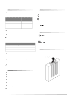
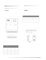
Module Components
Figure 1.
Module Circuit Board Components
Table 1. Module Component Descriptions
Component
Function
Unit Number DIP
Switches
Used for manually setting unit
numbers (SuperBus panels).
SuperBus 2000
Device ID Number
Label
Identifies unique device ID
number (SuperBus 2000
panels).
Software Version
Label
Identifies the installed
software version.
Green POWER
LED
Indicates module power status.
Red BUS LED
Flashes to indicate normal
communication to the panel
bus.
Wiring Terminals
Used for power, bus, and
hardwire zone input
connections.
SOFTWARE
VERSION LABEL
GREEN POWER
LED
UNIT NUMBER
DIP SWITCHES
WIRING
TERMINALS
9712G01A.DSF
RED BUS
STATUS LED
SUPERBUS 2000
DEVICE ID
NUMBER LABEL
8557109A.DS4