GE 60-774 Installation Instructions - Page 7
Programming and Testing, Troubleshooting, Specifications - receiver
 |
UPC - 046188091768
View all GE 60-774 manuals
Add to My Manuals
Save this manual to your list of manuals |
Page 7 highlights
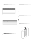
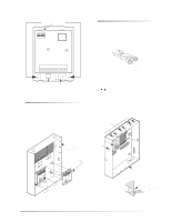
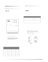
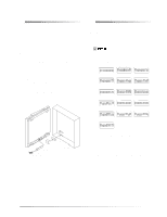
Programming and Testing Programming and Testing Specifications Refer to the specific panel Installation Instructions for adding (learning) hardwire sensors into panel memory and testing sensors. If the UltraGard or Concord system uses hardwire sensors only, turn off the Receiver Failure feature in the panel. Refer to the panel Installation Instructions for details. Troubleshooting Table 6 describes what to do if the module does not work correctly. Table 6. Troubleshooting Problem The green POWER LED stays off. The red BUS LED doesn't flash to indicate communication with the panel. The red BUS LED stays lit and blinks when zones are tripped, but the system does not respond. Action/Solution 1. Check for incorrect wiring connections. 2. Make sure panel AC power is applied and the backup battery(s) are connected. 3. If the LED still remains off, replace the module. 1. Verify that the panel recognizes the module by entering program mode (see specific panel Installation Instructions). 2. Check for incorrect wiring connections. 3. For Concord (software versions 1.0-1.6) and UltraGard panels make sure that module DIP switch 1 is set to "M." For Concord (software versions 2.0 or later) and Advent panels make sure that module DIP switch 1 is set to "A." 4. If the LED still doesn't flash, replace the module. 1. For Concord (software versions 1.0-1.6) or UltraGard systems, check for bus devices with the same unit number setting. 2. Re-initialize the panel by disconnecting and reconnecting panel power. 3. Make sure the zone has been "learned" into panel memory. 4. Verify that the panel recognizes the module by entering program mode (see specific panel Installation Instructions). 5. Remove zones and try installing the module without the zones. 6. Replace the module. Compatibility: Advent, Concord, UltraGard Power Requirements: 12 VDC nominal, 35 mA maximum (from panel) Panel Data Bus: ITI SuperBus and SuperBus 2000 digital data bus Inputs: Eight supervised, hardwire zones Storage Temperature: -30° to 140° F (-34° to 60° C) Operating Temperature: 32° to 120° F (0° to 49° C), up to 140° F (60° C) under temporary conditions Maximum Humidity: 90% relative humidity, non-condensing Dimensions: 5.25" x 4.125" x 1.0" (LxWxD) Color: Belgian gray Case Material: ABS plastic Installation: On wall or in panel cabinet mounting Listings: UL 365 Police Station Connected Burglar Alarm Units and Systems UL 609 Local Burglar Alarm Units and Systems UL 864 Control Units for Fire Protective Signaling Devices UL 985 Household Fire Warning System Units UL 1023 Household Burglar Alarm System Units UL 1610 Central Station Burglar Alarm Units (Commercial Burglary) UL 1637 Home Health Care Signaling Equipment CSFM California State Fire Marshall (applied for) FM Factory Mutual (applied for) MEA New York City Material Equipment Acceptance (applied for) DOD Sensitive Compartment Information Fac. (applied for) ULC Canada Commercial Fire/Burglary Warning (applied for) œÌi See specific panel Installation Instructions for complete UL installation requirements for the system you are installing. 7
-
 1
1 -
 2
2 -
 3
3 -
 4
4 -
 5
5 -
 6
6 -
 7
7 -
 8
8
 |
 |
