GE PB970 Installation Instructions - Page 3
Prepare The Opening, Minimum Dimensions Between Cooktop, Walls And Above The Cooktop
 |
View all GE PB970 manuals
Add to My Manuals
Save this manual to your list of manuals |
Page 3 highlights
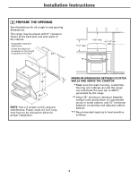
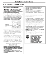
Installation Instructions 2 PREPARE THE OPENING See illustrations for all rough-in and spacing dimensions. The range may be placed with 0" clearance (flush) at the back wall and side walls of the cabinet. Acceptable electrical outlet area. Orient the electrical receptacle so the length is parallel to the floor. 31⁄4" 231⁄2" 31⁄4" **15" Min. **30" Min. ***6" Min. *0" *0" 30" 47" 36" 253⁄8" 45" NOTE: Use a 4′ power cord to prevent interference. Power cords 41⁄2 to 6′ long may have to be dressed to allow for proper installation. MINIMUM DIMENSIONS BETWEEN COOKTOP, 73⁄4" WALLS AND ABOVE THE COOKTOP: *** Make sure the wall covering, countertop, flooring and cabinets around the range can withstand the heat (up to 200°F) generated by the range. *** Allow 30" minimum clearance between surface units and bottom of unprotected wood or metal cabinet, and 15" minimum between countertop and adjacent cabinet bottom. *** Recommended spacing to heat-sensitive surfaces. 3
-
 1
1 -
 2
2 -
 3
3 -
 4
4 -
 5
5 -
 6
6 -
 7
7 -
 8
8 -
 9
9 -
10
-
11
-
12
 |
 |
