GE PEB2060SMSS Installation Instructions - Page 2
Cutout Dimensions, Install The Anti-tip Brace, Warning - trim kit
 |
UPC - 084691164166
View all GE PEB2060SMSS manuals
Add to My Manuals
Save this manual to your list of manuals |
Page 2 highlights
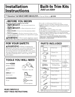
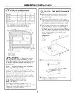
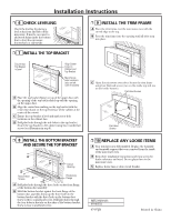
Installation Instructions ❒ 1 CUTOUT DIMENSIONS Models 27″ 30″ Height 163⁄4″ 163⁄4″ Width 251⁄2″ 251⁄2″ Depth (min.)* 191⁄2″ or 22″ 191⁄2″ or 22″ * Min. depth with receptacle outside cabinet 191⁄2″ Min. depth with receptacle inside cabinet 22″ 120 volt-60 Hertz grounded power receptacle 11⁄8″ Overlap Depth 27″ Models: 11⁄16″ overlap 30″ Models: 21⁄16″ overlap Height Width ❒ 2 INSTALL THE ANTI-TIP BRACE A Draw a line on the cutout floor at the center of the cutout, and extend the line 1/2″ down the face of the cabinet. B Draw a line on the top front face of the cabinet at the center of the cutout. The line should extend 1/2″ up the face of the cabinet. This center line will be used for mounting the top bracket (see step 7). C Fold or cut the front edge of the template, along the front guide line. Place the template flush along the front edge of the cutout floor, aligning the center line of the template with the center line of the cutout floor. Mark the center positions with an awl or center punch for the anti-tip brace location as shown. DIMENSIONS: A = 11⁄2″ D B = 3″ C = 183⁄16″ D = 1/2″ 1″ Clearance beyond trim frame (on all sides) Bottom of trim kit must be minimum of 36″ from floor 11⁄4″ Overlap 3″ Min. WARNING - This trim kit uses air flow from the top, bottom and sides of the trim frame. Blocking the air flow can cause the microwave to function improperly and may cause damage to the microwave. Allow a 1″ clearance beyond the edge of the trim frame to provide proper air flow. On 27″ models, allow 11⁄8″ at the top, 11⁄16″ on the sides and 11⁄4″ at the bottom for overlap of the Trim Frame over the edges of the cutout. On 30″ models, allow 11⁄8″ at the top, 21⁄16″ on the sides and 11⁄4″ at the bottom for overlap of the Trim Frame over the edges of the cutout. FOR INSTALLATION ABOVE A BUILT-IN OVEN: Microwave oven should be installed on a 3/8″ plywood base and supported by 2x4 or 1x2 equivalent runners on all sides. Base must be capable of supporting a minimum of 100 lbs. D D Drill two holes for the anti-tip brace. Round-head screws (2) Anti-Tip Brace E Install the anti-tip brace onto the cutout floor using two round-head screws. 2
-
 1
1 -
 2
2 -
 3
3 -
 4
4
 |
 |
