GE PGCS1RKZSS Use and Care Manual - Page 19
Installation Instructions, INSTALLING THE ANTI-TIP FLOOR BRACKET
 |
UPC - 084691085461
View all GE PGCS1RKZSS manuals
Add to My Manuals
Save this manual to your list of manuals |
Page 19 highlights
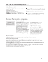
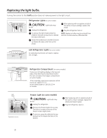
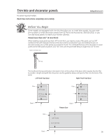
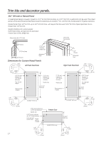
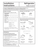
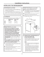
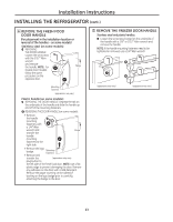
Installation Instructions INSTALLING THE ANTI-TIP FLOOR BRACKET (on 21 ft. models) WARNING Under certain circumstances, this refrigerator can tip forward. Injury to persons can result. Install Anti-Tip Bracket packed with this refrigerator. 1 MEASURE CABINET OPENING AVAILABLE VS. REFRIGERATOR WIDTH Measure width of cabinet opening where refrigerator will be placed, W. Be sure to account for any countertop overhang, baseboard thickness and any clearance desired. Width, W, should not be less than 36 inches. The refrigerator will be placed approximately in the middle of this opening. Rear Wall W REFRIGERATOR Baseboard Thickness or Countertop Overhang (Whichever Is Greater) Plus Any Desired Clearance RH Side Front 2 LOCATING THE ANTI-TIP FLOOR BRACKET A Place the anti-tip floor bracket locator template (included inside the anti-tip kit) onto the floor up against the rear wall, within W, and in line with the desired location of the RH side of the refrigerator (see Figure 1). Figure 1 - Installation Overview Floor - Concrete (2 Holes) Floor - Wood 2 Wall Holes Floor Bracket to Install (2 Holes) RH Holes 71⁄4″ Base Bracket on the Refrigerator RH Side of Refrigerator Rear RH Corner of Cabinet Wall Locator Template Sheet B Place the anti-tip floor bracket onto the locator template with its RH floor holes lined up with the floor holes indicated on the template sheet, approximately 71⁄4″ from the edge of the sheet or the RH side of the refrigerator. C Hold down in position and use the anti-tip floor bracket as a template for marking the holes based upon your configuration and type of construction as shown in Step 3. Mark the hole locations with a pencil, nail or awl. NOTE: • It is REQUIRED to use at least 2 screws to mount the floor bracket (one on each side of the anti-tip floor bracket). Both must be into either the wall or the floor. Figure 2 indicates all the acceptable mounting configurations for screws. Identify the screw holes on the anti-tip floor bracket for your configuration. 19
-
 1
1 -
2
-
3
-
4
-
5
-
6
-
7
-
8
-
9
-
10
-
11
-
12
-
13
-
 14
14 -
 15
15 -
 16
16 -
 17
17 -
 18
18 -
 19
19 -
 20
20 -
 21
21 -
 22
22 -
 23
23 -
 24
24 -
25
-
26
-
27
-
28
-
29
-
30
-
31
-
32
-
33
-
34
-
35
-
36
-
37
-
38
-
39
-
40
-
41
-
42
-
43
-
44
-
45
-
46
-
47
-
48
-
49
-
50
-
51
-
52
-
53
-
54
-
55
-
56
-
57
-
58
-
59
-
60
-
61
-
62
-
63
-
64
-
65
-
66
-
67
-
68
-
69
-
70
-
71
-
72
-
73
-
74
-
75
-
76
-
77
-
78
-
79
-
80
-
81
-
82
-
83
-
84
-
85
-
86
-
87
-
88
-
89
-
90
-
91
-
92
-
93
-
94
-
95
-
96
-
97
-
98
-
99
-
100
-
101
-
102
-
103
-
104
-
105
-
106
-
107
-
108
-
109
-
110
-
111
-
112
-
113
-
114
-
115
-
116
-
117
-
118
-
119
-
120
-
121
-
122
-
123
-
124
-
125
-
126
-
127
-
128
-
129
-
130
-
131
-
132
-
133
-
134
-
135
-
136
 |
 |
