GE PNM1871SMSS Installation Instructions - Page 10
Aligning the Wall Plate, Set the mounting plate aside.
 |
UPC - 084691164265
View all GE PNM1871SMSS manuals
Add to My Manuals
Save this manual to your list of manuals |
Page 10 highlights
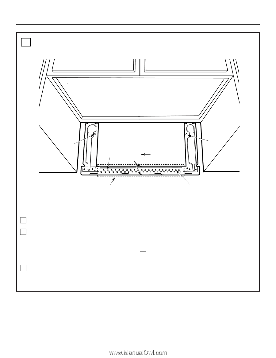
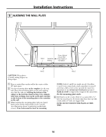
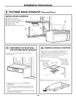
Installation Instructions D. ALIGNING THE WALL PLATE Hole A Hole C Centerline Notches Draw a Vertical Line on Wall from Center of Top Cabinet Hole B CAUTION: Wear gloves to avoid cutting fingers on sharp edges. Area E 1 Draw a vertical line on the wall at the center of the 30″ wide space. 2 Use the mounting plate as the template for the rear wall. Place the mounting plate on the wall, making sure that the tabs are touching the bottom of the cabinet or the level line drawn in Step C for cabinets with front overhang. Line up the notch and centerline on the bottom of the mounting plate to the centerline on the wall. 3 While holding the mounting plate with one hand, draw circles on the wall at holes A, B, C and D (see illustration above/actual plate marked with arrows). Four holes must be used for mounting. Hole D NOTE: Holes C and D are inside area E. If neither C nor D is in a stud, find a stud somewhere in area E and draw a fifth circle to line up with the stud. It is important to use at least one wood screw mounted firmly in a stud to support the weight of the microwave. Set the mounting plate aside. 4 Drill holes on the circles. If there is a stud, drill a 3⁄16″ hole for wood screws. For holes that don't line up with a stud, drill a 5⁄8″ hole for toggle bolts. NOTE: DO NOT MOUNT THE PLATE AT THIS TIME. 10
-
 1
1 -
2
-
3
-
4
-
 5
5 -
 6
6 -
 7
7 -
 8
8 -
 9
9 -
 10
10 -
 11
11 -
 12
12 -
 13
13 -
 14
14 -
 15
15 -
16
-
17
-
18
-
19
-
20
-
21
-
22
-
23
-
24
-
25
-
26
-
27
-
28
-
29
-
30
-
31
-
32
-
33
-
34
-
35
-
36
-
37
-
38
-
39
-
40
-
41
-
42
-
43
-
44
-
45
-
46
-
47
-
48
 |
 |