GE WSM2700WWW Installation Instructions - Page 2
Installation Instructions
 |
View all GE WSM2700WWW manuals
Add to My Manuals
Save this manual to your list of manuals |
Page 2 highlights
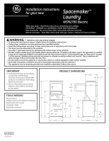
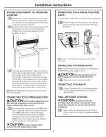
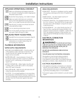
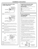
Installation Instructions UNPACKING SPACEMAKER™ 1 Remove tape and two corner pads from rear bottom corners of appliance. 2 Using the four shipping corner posts, lay the appliance on its left side so the shipping base does not rest on the floor. Plastic spacer block Shipping blocks Shipping Rear vent clips only Mechanism shipping bolt Foam shipping pad Drain hose Shipping carton corner posts 3 Remove the foam shipping pad. 4 Remove the washer shipping bolt using the ratchet with 3/8″ socket and remove the plastic spacer block using the slip-joint pliers. 5 Return the appliance to the upright position and locate it in the general area to be installed. Provide enough space at the rear for installing the water inlet hose. 6 Untape and open the washer lid. 7 Remove: a. foam tub blocking pad b. foam shipping blocks from rear of unit c. tape from dryer door d. foam dryer support pads e. inlet hoses f. From the back of the washer, remove only the WIRE shipping clips that secure the drain hose to the left side of the washer backsheet. DO NOT REMOVE THE PLASTIC CLAMPS on the right side of the washer. These clamps form a standpipe to prevent water siphoning. UNPACKING SPACEMAKER™ (CONT.) NOTE: The tub blocking pad, shipping bolt and plastic spacer should be retained for use if the appliance is transported at a later date. 8 Form a "U" shape on the end of the drain hose with hose pointed toward the drain. For an installation requiring a longer drain hose, use WH41X0387 (approximately 112″). This drain hose attaches directly to the pump and should be installed by a qualified technician. INLET HOSE CONNECTIONS 9 Remove the inlet hoses and rubber washers from the plastic bag. 9A Install the rubber washers in each end of the inlet hoses. 9B Carefully connect the inlet hose marked "HOT" to the bottom outlet of the water valve. Tighten by hand; then tighten another 2/3 turn with pliers. Carefully connect the other inlet hose to the top outlet of the water valve. Tighten by hand; then tighten another 2/3 turn with pliers. POWER CORD CONNECTION SEE ELECTRICAL CONNECTION INFORMATION Tub blocking pad Dryer support pads 2
-
 1
1 -
 2
2 -
 3
3 -
 4
4 -
 5
5 -
 6
6 -
 7
7 -
 8
8
 |
 |
