GE WSM2700WWW Installation Instructions - Page 7
Exhaust Information Cont. - parts
 |
View all GE WSM2700WWW manuals
Add to My Manuals
Save this manual to your list of manuals |
Page 7 highlights
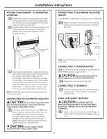
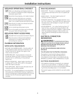
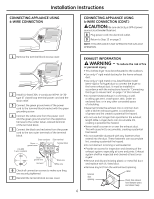
Installation Instructions EXHAUST INFORMATION (CONT.) EXHAUST DUCT LENGTH INFORMATION • The MAXIMUM ALLOWABLE length of the exhaust system depends upon the type of duct, number of turns, the type of exhaust hood (wall cap) and all conditions noted below. More than three 90° turns are not recommended. Rear vent only NUMBER OF 90° TURNS 0 1 2 3 EXHAUST HOOD TYPE A B 56 ft. 46 ft. 34 ft. 32 ft. 42 ft. 36 ft. 28 ft. 18 ft. A B 4″ 21⁄ 2″ Maximum length of 4″ diameter rigid metal duct HOOD OR WALL CAP • Terminate in a manner to prevent back drafts or entry of birds or other wildlife. • Termination should present minimal resistance to the exhaust airflow and should require little or no maintenance to prevent clogging. • Never install a screen over the exhaust duct. • Wall caps must be installed at least 12″ above ground level or any other obstruction with the opening pointed down. TURNS OTHER THAN 90° • One turn of 45° or less may be ignored. • Two 45° turns should be treated as one 90°. CONNECTING THE DRYER TO HOUSE VENT Rigid Metal Transition Duct • For best drying performance, a rigid metal transition duct is recommended. • Rigid metal transition ducts reduce the risk of crushing and kinking. UL-Listed Flexible Metal (Semi-Rigid) Transition Duct • If rigid metal duct cannot be used, then UL-listed flexible metal (semi-rigid) ducting can be used (Kit WX08X10077). • Never install flexible metal duct in walls, ceilings, floors or other enclosed spaces. • Total length of flexible metal duct should not exceed 8 feet (2.4 m). • For many applications, installing elbows at both the dryer and the wall is highly recommended. Elbows allow the dryer to sit close to the wall without kinking and or crushing the transition duct, maximizing drying performance. • Avoid resting the duct on sharp objects. 7 CONNECTING THE DRYER TO HOUSE VENT (CONT.) UL-Listed Flexible Metal (Foil-Type) Transition Duct • In special installations, it may be necessary to connect the dryer to the house vent using a flexible metal (foil-type) duct. A UL-listed flexible metal (foil-type) duct may be used ONLY in installations where rigid metal or flexible metal (semi-rigid) ducting cannot be used AND where a 4" diameter can be maintained throughout the entire length of the transition duct. • In Canada and the United States, only the flexible metal (foil-type) ducts that comply with the "Outline for Clothes Dryer Transition Duct, Subject 2158A" shall be used. • Never install flexible metal duct in walls, ceilings, floors or other enclosed spaces. • Total length of flexible metal duct should not exceed 8 feet (2.4 m). • Avoid resting the duct on sharp objects. For best drying performance: 1. Slide one end of the duct over the clothes dryer outlet pipe. 2. Secure the duct with a clamp. 3. With the dryer in its permanent position, extend the duct to its full length. Allow 2″ of duct to overlap the exhaust pipe. Cut off and remove excess duct. Keep the duct as straight as possible for maximum airflow. 4. Secure the duct to the exhaust pipe with the other clamp. SEALING OF JOINTS • All joints should be tight to avoid leaks. NOTE: The male end of each section of duct must point away from the dryer. • Do not assemble ductwork with fasteners that extend into the duct. They will serve as a collection point for lint. • Duct joints can be made air- and moisture-tight by wrapping the overlapped joints with duct tape. INSULATION • Ductwork that runs through an unheated area or is near an air conditioning duct should be insulated to reduce condensation and lint buildup. PARTS AVAILABLE FROM LOCAL SERVICE ORGANIZATIONS • Rigid Metal Duct Components WX8X63 WX8X64 WX8X51 WX8X59 4″ x 1′ Duct 4″ x 2′ Duct 4″ Elbow 4″ Aluminum Hood • Flexible Metal Duct Components WX8X58 4″ Clamps (2) WX8X59 4″ Aluminum Hood WX08X10077 6′ UL-Listed, Flexible Metal (Semi-Rigid) Duct, 2 Clamps, 2 Close Elbows
-
 1
1 -
 2
2 -
 3
3 -
 4
4 -
 5
5 -
 6
6 -
 7
7 -
 8
8
 |
 |
