Gigabyte GA-5YASV-RH Manual
Gigabyte GA-5YASV-RH Manual
 |
View all Gigabyte GA-5YASV-RH manuals
Add to My Manuals
Save this manual to your list of manuals |
Gigabyte GA-5YASV-RH manual content summary:
- Gigabyte GA-5YASV-RH | Manual - Page 1
GA-5YASV-RH Xeon® Processor Motherboard USER'S MANUAL Xeon® Processor Motherboard Rev. 1001 * The WEEE marking on the product indicates this product must not be disposed of with user's other household waste and must be handed over - Gigabyte GA-5YASV-RH | Manual - Page 2
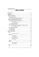
GA-5YASV-RH Motherboard Components 8 Chapter 2 Hardware Installation Process 10 2-1: Installing Processor and CPU Haet Sink 10 2-1-1: Installing CPU ...10 2-1-2: Installing Cooling Fan 11 2-2: Install Memory BIOS Setup 34 Main ...36 Advanced Processor Options 39 Advanced 41 Memory - Gigabyte GA-5YASV-RH | Manual - Page 3
English Table of Content Chapter 4 INTEL RAID BIOS Configuration 67 Chapter 5 Appendix 72 3 - Gigabyte GA-5YASV-RH | Manual - Page 4
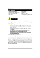
English GA-5YASV-RH Motherboard Item Checklist The GA-5YASV-RH motherboard IDE (ATA133 ) cable x 1 / Floppy cable x 1 CD for motherboard driver & utility USB cable x 1 Serial ATA cable x 6 I/O Shield Kit SATA Power cable x 3 Ga-5YASV-RH Quick Reference Guide WARNING! Computer motherboards and - Gigabyte GA-5YASV-RH | Manual - Page 5
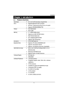
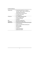
Chapter 1 Introduction Introduction 1.1 Features Summary Form Factor CPU Chipset Memory I/O Control Expansion Slots SATA RAID Controller On-Board Graphic On-Board Peripherals 9.6" x 9.6" M ATX form factor, 6 layers PCB. Supports single Intel® Xeon® processor Intel Xeon® Quad-Core processor in - Gigabyte GA-5YASV-RH | Manual - Page 6
English GA-5YASV-RH Motherboard Hardware Monitor On-Board LAN BIOS Special Features Additional Features Enhanced features with CPU Vcore, 1.2V reference, VCC3 (3.3V) , VBAT3V, +5VSB, CPU Temperature, and System Temperature Values viewing CPU/Power/System Fan Revolution Detect CPU shutdown when - Gigabyte GA-5YASV-RH | Manual - Page 7
Introduction 7 - Gigabyte GA-5YASV-RH | Manual - Page 8
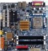
English GA-5YASV-RH Motherboard 1.2 GA-5YASV-RH Motherboard Components 1. CPU 2. Intel 3200 3. Intel ICH9R 4. XGI Volari Z9s 5. . SATA2 Connector 17. SATA3 Connector 18. SATA4 Connector 19. SATA5 Connector 20. CPU fan cable connector 21. System fan cable connector 22. Front fan cable connector 23 - Gigabyte GA-5YASV-RH | Manual - Page 9
Introduction 34 35 36 23 37 4 57 33 33 21 25 26 27 28 8 40 11 20 24 1 2 12 13 3 38 22 29 30 31 32 9 6 10 39 19 18 17 16 15 14 9 - Gigabyte GA-5YASV-RH | Manual - Page 10
GA-5YASV-RH Motherboard Chapter 2 Hardware Installation Process 2-1: Installing Processor and CPU Haet CPU type is supported by the motherboard. 5. If you do not match the CPU socket Pin 1 and CPU cut edge well, it may damage the CPU. Please change the insert orientation. 2-1-1: Installing CPU - Gigabyte GA-5YASV-RH | Manual - Page 11
2-1-2: Installing Cooling Fan Hardware Installation Process Step 1 Attach the heat sink clip to the processor socket. Step 2 Place the cooling fan on the heat sink. Step 3 Secure the cooing fan with screws. Step 4 Connect processor fan can cable to the processor fanconnector 11 - Gigabyte GA-5YASV-RH | Manual - Page 12
GA-5YASV-RH Motherboard 2-2: Install Memory Modules Before installing the processor and heatsink, adhere to the following warning: When DIMM LED is ON, do not install/remove DIMM from socket. GA-5YASV-RH has 4 dual inline memory module (DIMM) sokcets. It supports Dual Channels Technology. The BIOS - Gigabyte GA-5YASV-RH | Manual - Page 13
Table 1. Supported DIMM Module Type Size 256MB 512MB 1GB Organization 8MB x 8 x 4 bks 16MB x 4 x 4bks 16MB x 8 x 4bks 32MB x 4 x 4bks 32MB x 8 x 4bks 64MB x 4 x 4bks Hardware Installation Process RAM Chips/ - Gigabyte GA-5YASV-RH | Manual - Page 14
English GA-5YASV-RH Motherboard 2-3: Connect ribbon cables, cabinet wires, and power supply 2-3-1 : I/O Back Panel Introduction 14 - Gigabyte GA-5YASV-RH | Manual - Page 15
, mouse, scanner, zip, speaker...etc. have a standard USB interface. Also make sure your OS supports USB controller. If your OS does not support USB controller, please contact OS vendor for possible patch or driver updated. For more information please contact your OS or device(s) vendors. LAN LED - Gigabyte GA-5YASV-RH | Manual - Page 16
English GA-5YASV-RH Motherboard 2-4: Connectors Introduction 18 16 2 15 11 20 12 13 14 10 8 6 17 9 7 19 5 4 3 1 1. ATX1 2. ATX2 3. IDE1 (IDE cable connector) 4. FDC1 (Floppy cable connector) 5. SATA 0 (SATA - Gigabyte GA-5YASV-RH | Manual - Page 17
GND GND GND -5V +5V +5V +5V GND 42 31 Pin No. 1 2 3 4 Definition GND GND +12V +12V This connector (ATX +12V) is used only for CPU Core Voltage. 17 - Gigabyte GA-5YASV-RH | Manual - Page 18
English GA-5YASV-RH Motherboard 3 ) IDE1 (IDE Connector) Please connect first harddisk to IDE1. The red stripe of the ribbon cable must be the same side with the Pin1. 39 40 1 2 4 ) FDC1 (Floppy Connector) Please connect the floppy drive ribbon cables to FDD. It supports 720K,1.2M,1.44M and 2. - Gigabyte GA-5YASV-RH | Manual - Page 19
Connector Introduction 5/ 6/ 7/ 89/10 ) SATA 0~5 (Serial ATA cable connectors) You can connect the Serial ATA device to this connector, it provides you high speed transfer rates (3.0Gb/sec). 1 Pin No. Definition 1 GND 2 TXP 3 TXN 4 GND 5 RXN 6 RXP 7 7 GND 11 ) COM2 (Serial port - Gigabyte GA-5YASV-RH | Manual - Page 20
English GA-5YASV-RH Motherboard 12/ 13 ) F_USB1/2 (USB cable connectors) Be HBA and 1 is driven by the backplane. Typically, the HBA is a storage controller located inside a server, desktop, rack or workstation computer that interfaces with Hard disk drives (HDDs) to store and retrieve data - Gigabyte GA-5YASV-RH | Manual - Page 21
fan cable connector) Please note, a proper installation of the CPU cooler is essential to prevent the CPU from running under abnormal condition or damaged by overheating.The CPU fan connector supports Max. current up to 1A . Pin No. Definition 1 GND 1 2 12V 3 Sense 4 Control 16/ 17/18 - Gigabyte GA-5YASV-RH | Manual - Page 22
English GA-5YASV-RH Motherboard 16 ) F_Panel (2X12 Pins Front Panel connector) Please connect the power LED, PC speaker, reset switch and power switch of your chassis front panel to - Gigabyte GA-5YASV-RH | Manual - Page 23
English GA-5YASV-RH Motherboard 17 ) Battery If you want to erase CMOS... 1.Turn OFF the computer and unplug the power cord. 2.Remove the battery, only with the same or equivalent type recommended by the manufacturer. Dispose of used batteries according to the manufacturer's instructions. 23 - Gigabyte GA-5YASV-RH | Manual - Page 24
English GA-5YASV-RH Motherboard 2-5: Jumper Setting 2 4 3 1 1. CLR_CMOS 2. PWR_JP1 3. PWR_JP2 4. PWR_JP3 5. PWR_JP5 5 6 8 10 79 6. MODEL_0 7. MODEL_1 8. MODEL_2 9. RECOVERY1 10. PASSWORD1 24 - Gigabyte GA-5YASV-RH | Manual - Page 25
Jumper Setting 1 ) CLR_CMOS1 (Clear CMOS jumper) You may clear the CMOS data to restore its default values by this jumper. Default value doesn't include the "Shunter" to prevent from improper use this jumper. To clear CMOS, temporarily short 1-2 pin. 1 1-2 Close: Normal (Default setting) 1 2-3 - Gigabyte GA-5YASV-RH | Manual - Page 26
GA-5YASV-RH Motherboard 2 ) PWR_JP1 (USB power source selection jumper) English 1 1-2 close: Rear USB powered when system shut down (Default setting) 1 2-3 close: Disable this function 26 - Gigabyte GA-5YASV-RH | Manual - Page 27
3 ) PWR_JP2 (USB2 power source selection jumper) Jumper Setting 1 1-2 close: Front USB2 powered when system shut down. (Default setting) 1 2-3 close: Disable this function. 27 - Gigabyte GA-5YASV-RH | Manual - Page 28
English GA-5YASV-RH Motherboard 4 ) PWR_JP3 (USB1 power source selection jumper) 1 1-2 close: Front USB1 powered when system shut down. (Default setting) 1 2-3 close: Disable this function. 28 - Gigabyte GA-5YASV-RH | Manual - Page 29
Jumper Setting 5 ) PWR_JP5 (PS2 Keyboard/Mouse power source selection jumper) 1 1-2 close: Keyboard/mouse powered when system shut down. (Default setting) 1 2-3 close: Disable this function. 29 - Gigabyte GA-5YASV-RH | Manual - Page 30
GA-5YASV-RH Motherboard 6/ 7/ 8 ) Model_0/ Model_1/ Model_2 (Identify BIOS version jumper) English 1 Model _0 default setting: 1-2 close 1 Model _1 default setting: 2-3 close 1 Model _2 default setting: 2-3 close 30 - Gigabyte GA-5YASV-RH | Manual - Page 31
GA-5YASV-RH Motherboard 9 ) RECCOVERY1 ( BIOS recovery jumper) English 1 1-2 Close: Enable BIOS Recovery function. 1 2-3 Close: Normal (Default setting) 31 - Gigabyte GA-5YASV-RH | Manual - Page 32
English GA-5YASV-RH Motherboard 10 ) PASSWORD1 (Skip password jumper) 1 1-2 Close: Skip Supervisor Password in BIOS setup menu 1 2-3 Close: Normal (Default setting) 32 - Gigabyte GA-5YASV-RH | Manual - Page 33
2-6: Block Diagram CLOCK GENERATOR ICS9LPR505-2 INTEL LGA775 Xeon Wolfdale/Concore/ Kentsfield/Yorkfield FSB 1333/1066/800 Block Diagram VRD 11.0 ISL6612/6326CR PCIE x8 Slot PCIE x8 MCH BIGBY-V (INTEL 3200) DMI_PN_0~3 DMI Control Bus CHANNEL A DDR2 667/800 Un-Buffered ECC DIMM x 2 CHANNEL B - Gigabyte GA-5YASV-RH | Manual - Page 34
GA-5YASV-RH Motherboard Chapter 3 BIOS Setup BIOS Setup is an overview of the BIOS Setup Program. The program that Status Page Setup Menu and Option Page Setup Menu - Exit current page and return to Main Menu Increase the numeric value or make changes Decrease the numeric value - Gigabyte GA-5YASV-RH | Manual - Page 35
appropriate keys to use and the possible selections for the highlighted item. To exit the Help Window press . z Main This setup page includes all the items in standard compatible BIOS. z Advanced This setup page includes all the items of AMI special enhanced features. (ex: Auto detect fan and - Gigabyte GA-5YASV-RH | Manual - Page 36
GA-5YASV-RH Motherboard Main Once you enter Phoenix BIOS Setup Utility, the Main Menu (Figure 1) will appear on the screen. Use arrow keys to select among the items and press to accept or enter the sub-menu. Figure 1: Main System Time The time is calculated based on the 24-hour military time - Gigabyte GA-5YASV-RH | Manual - Page 37
BIOS Setup Legacy Diskette A This category identifies the type of floppy disk drive 1 to 6 that has been installed in the computer. There are two types: auto type, and manual type. Manual type is user-definable; Auto type which will automatically detect HDD type. Note that the specifications of - Gigabyte GA-5YASV-RH | Manual - Page 38
GA-5YASV-RH Motherboard TYPE 1-39: Predefined types. Users: Set parameters by User. Auto: Set parameters data transfer from and to the device occurs multiple sectors at a time if the device supports it. LBA Mode 32-Bit I/O Transfer Mode Ultra DMA Mode This field shows if the device type in - Gigabyte GA-5YASV-RH | Manual - Page 39
Processor Options BIOS Setup Figure 1-1: Advanced Processor Option Advanced Processor Option This category includes the information of CPU Speed, Processor CPUID, and Processor L2 Cache. Setup menu for C1 Enhanced Mode, No Execute Mode Memory Protection, Intel EIST Support, Intel Virtualization - Gigabyte GA-5YASV-RH | Manual - Page 40
GA-5YASV-RH Motherboard No Execute Mode Mem. Protection Enabled Enable No Execute Mode Memory Protection function. (Default setting) Disabled Disables No Execute Mode Memory Protection function. Intel EIST Support Select the Power Management desired: Enabled C states and GV1/GV3 are enabled. - Gigabyte GA-5YASV-RH | Manual - Page 41
Advanced BIOS Setup About This Section: Advanced With this section, allowing user to configure your system for basic operation. User can change the processor options, chipset configuration, PCI configuration and chipset control. Figure 2: Advanced 41 - Gigabyte GA-5YASV-RH | Manual - Page 42
GA-5YASV-RH Motherboard Memory Configuration Figure 2-1: Memory Configuration Installed Memory/Available to OS/Used by devices/ DIMM Group 1,2,3,4 Status These category is display-only which is determined by POST (Power On Self Test) of the BIOS. Memory Reset Yes No Select 'Yes', system will - Gigabyte GA-5YASV-RH | Manual - Page 43
PCI Configuration BIOS Setup Figure 2-2: PCI Configuration Embedded NIC Onboard LAN1 Control Enabled Enable onboard LAN device. (Default setting) Disabled Disable this function. LAN1 Option ROM Scan Enabled - Gigabyte GA-5YASV-RH | Manual - Page 44
GA-5YASV-RH Motherboard PCI Slot 1/2/3/4 Option ROM Enabled Enableing this item to initialize device expansion ROM. (Defualt setting) Disabled Disable this function. 44 - Gigabyte GA-5YASV-RH | Manual - Page 45
I/O Device Configuration BIOS Setup Figure 2-3: I/O Device Configuration 45 - Gigabyte GA-5YASV-RH | Manual - Page 46
GA-5YASV-RH Motherboard Serial Port A This allows users to configure serial prot A by using this option. Enabled Enable the configuration (Default setting) Disabled Disable the configuration. Base I/O Address/ - Gigabyte GA-5YASV-RH | Manual - Page 47
Mode This option allows user to set Parallel Port transfer mode. BIOS Setup Bi-directional Use this setting to support bi-directional transfers on the parallel port. (Default setting) EPP Using Parallel port as Enhanced Parallel Port. ECP Using Parallel port as Extended Capabilities Port. - Gigabyte GA-5YASV-RH | Manual - Page 48
GA-5YASV-RH Motherboard Serial ATA Enabled Enables on-board serial ATA function. ( RAID Enable Enabled Enabled SATA RAID function. Disabled Disable this function. (Default setting) ` SATA AHCI Enable Enabled Disabled Set this item to enable SATA AHCI function for WinXP-SP1+IAA driver supports - Gigabyte GA-5YASV-RH | Manual - Page 49
Advanced Chipset Control BIOS Setup Figure 2-4: Advanced Chipset Control Enable Multimedia Timer Enabled Enable Multimedia Timer support. Disabled Disable this function. (Default setting) Wake On LAN / PME This option allow user to determine the action of the system when a LAN/PME wake - Gigabyte GA-5YASV-RH | Manual - Page 50
GA-5YASV-RH Motherboard Wake On Ring This option allow user to determine the action of the system power is off and the modem is ringing. Enabled Enable Wake - Gigabyte GA-5YASV-RH | Manual - Page 51
Hardware Monitor BIOS Setup Figure 2-5: Hardware Monitor CPU / Motherboard/ DDR Temperature Display the current CPU temperature, Motherboard, and Ambient temperature. Voltage Monitor: DDR1V8, VCC3V3, VCORE, 12V2, 5V Detect system's voltage status automatically. FAN Monitor: CPU Fan/ System Fan/ - Gigabyte GA-5YASV-RH | Manual - Page 52
GA-5YASV-RH Motherboard Reset Configuration Data Yes Reset all configuration data. No Do not make any changes (MP) specification revision level. Some operating system will require 1.1 for compatibility reasons. 1.4 Support MPS Version 1.4 . (Default setting) 1.1 Support M PS Version 1.1. 52 - Gigabyte GA-5YASV-RH | Manual - Page 53
Security BIOS Setup * About This Section: Security In this section, user can in lengh and press . The password typed now will clear any previously entered password from the CMOS memory. You will be asked to confirm the entered password. Type the password again and press . You may - Gigabyte GA-5YASV-RH | Manual - Page 54
GA-5YASV-RH Motherboard Set Supervisor Password You can install and change this options for the setup menus. Type the password up to 6 characters in lengh and press . The password typed now will clear any previously entered password from the CMOS memory. You will be asked to confirm the - Gigabyte GA-5YASV-RH | Manual - Page 55
Server BIOS Setup Figure 4: Server 55 - Gigabyte GA-5YASV-RH | Manual - Page 56
GA-5YASV-RH Motherboard System Management Figure 4-1: System Management Server Management This category allows user to view the server management features. Including information of BIOS Version. All items in this menu cannot be modified in user's mode. If any items require changes, please consult - Gigabyte GA-5YASV-RH | Manual - Page 57
Setup Figure 4-2: Console Redirection BIOS Redirection Port If this option is set to enabled, it will use a port on the motherboard. Serial Port A Use Serial Port as he COMA port address. Serial Port B Use Serial Port as he COMB port address. Disabled Disable this function. (Default - Gigabyte GA-5YASV-RH | Manual - Page 58
GA-5YASV-RH Motherboard Flow Control This option provide user to enable the flow control function. None Not supported. XON/OFF Software control. CTS/RTS Hardware control. (Default setting) Terminal Type This option allows user to select the specified terminal type. This is defined - Gigabyte GA-5YASV-RH | Manual - Page 59
BIOS Setup Assert NMI on SERR If thisoption is set to enabled, PCI bus system error (SERR) is enabled and is routed to NMI. Enabled Enable - Gigabyte GA-5YASV-RH | Manual - Page 60
GA-5YASV-RH Motherboard AC-LINK This option provides user to set the mode of operation if an AC / power loss occurs. Power On System power state when AC - Gigabyte GA-5YASV-RH | Manual - Page 61
Boot BIOS Setup Figure 5: Boot Boot Priority Order This field determines which type of device the system attempt to boot from after PhoenixBIOS Post completed. Specifies the - Gigabyte GA-5YASV-RH | Manual - Page 62
GA-5YASV-RH Motherboard Exit Figure 6: Exit * About This Section: Exit Once you have changed all of the set values in the BIOS setup, you should save your changes and exit BIOS setup program. Select "Exit" from the menu bar, to display the following sub-menu. Exit Saving Changes Exit Discarding - Gigabyte GA-5YASV-RH | Manual - Page 63
BIOS Setup Exit Saving Changes This option allows user to exit system setup with saving the changes. Press on the present setting values tha user made in this time into CMOS. Therefore, whenyou boot up your computer next time, the BIOS will re-configure your system according data in CMOS. 63 - Gigabyte GA-5YASV-RH | Manual - Page 64
GA-5YASV-RH Motherboard Exit Discarding Changes This option allows user to exit system setup without changing any previous settings values in CMOS. The previous selection remain in effect. - Gigabyte GA-5YASV-RH | Manual - Page 65
BIOS Setup Discard Changes This option allows user to load previos values from CMOS for all setup item. When you press on this item, you will get a confirmation dialog box with a message as below: 65 - Gigabyte GA-5YASV-RH | Manual - Page 66
GA-5YASV-RH Motherboard Save Changes This option allows user to save setup dat ato CMOS. When you press on this item, you will get a confirmation dialog box with a message as below: Press [Yes] to save setup daya to CMOS. 66 - Gigabyte GA-5YASV-RH | Manual - Page 67
(C) 2003-04 Intel Corporation. All Rights Reversed. [ MAIN MENU ] 1. Create RAID Volume 2. Delete RAID Volume 3. Reset Disks to Non-RAID 4. Exit RAID Volumes : None Defined. [ DISK/VOLUME INFORMATION ] Physical Disks : Port Driver Model 0 ST3120026AS 1 ST3120026AS Serial # 3JT329JX 3JT354CP - Gigabyte GA-5YASV-RH | Manual - Page 68
GA-5YASV-RH Motherboard Create RAID Volume Press Enter under Create RAID Volume to set up RAID. Intel(R) Matrix Storage Manager option ROM V5.0.0.1011 ICH7R wRAID5 Copyright(C) 2003-04 Intel Corporation. All Rights Reversed. [ CREATE VOLUME MENU ] Name : RAID Level : Disks : Strip Size : Capacity - Gigabyte GA-5YASV-RH | Manual - Page 69
INTEL RAID BIOS Configuration The KB is a unit of Strip Size. You can set disk block ) Select Disks 128KB 223.5 GB Create Volume [ HELP ] The following are typical values: RAID 0 - 128KB RAID 1 - 64KB RAID 5 - 64KB [KL]-Change [TAB]-Next [ESC]-Previous Menu [ENTER]-Select Intel(R) Matrix - Gigabyte GA-5YASV-RH | Manual - Page 70
GA-5YASV-RH Motherboard Press Enter under the Create Volume item. Intel(R) Matrix Storage Manager option ROM V5.0.0.1011 ICH7R wRAID5 Copyright(C) 2003-04 Intel Corporation. All Rights Reversed. [ CREATE VOLUME MENU ] Name : RAID Level : Disks : Strip Size : Capacity : RAID_Volume0 RAID0(Stripe) - Gigabyte GA-5YASV-RH | Manual - Page 71
key and follow the instructions on the screen. Intel(R) Matrix Storage Manager option ROM V5.0.0.1011 ICH7R wRAID5 Copyright(C) 2003-04 Intel Corporation. All Rights Reversed. [ MAIN MENU ] 1. Create RAID Volume 2. Delete RAID Volume 3. Reset Disks to Non-RAID 4. Exit RAID Volumes : ID Name - Gigabyte GA-5YASV-RH | Manual - Page 72
GA-5YASV-RH Motherboard RCehvaispitoenr H5istAoprypendix Appendix : Acronyms Acronyms Meaning ACPI Advanced Configuration and Power Interface APM Advanced Power Management AGP Accelerated Graphics Port AMR Audio Modem Riser ACR Advanced Communications Riser BBS BIOS Boot Specification - Gigabyte GA-5YASV-RH | Manual - Page 73
PCI A.G.P. Controller Power-On Self Test Peripheral Component Interconnect Rambus in-line Memory Module Special Circumstance Instructions Single Edge Contact Cartridge Static Random Access Memory Symmetric Multi-Processing System Management Interrupt Universal Serial Bus Voltage ID Appendix 73
-
 1
1 -
 2
2 -
 3
3 -
 4
4 -
 5
5 -
 6
6 -
 7
7 -
8
-
9
-
10
-
11
-
12
-
13
-
14
-
15
-
16
-
17
-
18
-
19
-
20
-
21
-
22
-
23
-
24
-
25
-
26
-
27
-
28
-
29
-
30
-
31
-
32
-
33
-
34
-
35
-
36
-
37
-
38
-
39
-
40
-
41
-
42
-
43
-
44
-
45
-
46
-
47
-
48
-
49
-
50
-
51
-
52
-
53
-
54
-
55
-
56
-
57
-
58
-
59
-
60
-
61
-
62
-
63
-
64
-
65
-
66
-
67
-
68
-
69
-
70
-
71
-
72
-
73
 |
 |

USER’S MANUAL
GA-5YASV-RH
Xeon
®
Processor Motherboard
Xeon
®
Processor Motherboard
Rev. 1001
*
The WEEE marking on the product indicates this product must not be disposed of with
user's other household waste and must be handed over to a designated collection point
for the recycling of waste electrical and electronic equipment!!
*
The WEEE marking applies only in European Union's member states.