Gigabyte GA-7N400 User Manual
Gigabyte GA-7N400 Manual
 |
View all Gigabyte GA-7N400 manuals
Add to My Manuals
Save this manual to your list of manuals |
Gigabyte GA-7N400 manual content summary:
- Gigabyte GA-7N400 | User Manual - Page 1
) mode AGP slot, but they support 2X(3.3V) only. The GA-7N400 Pro2 / GA-7N400 / GA-7N400-L (or any AGP 4X/8X only) motherboards might not function properly, If you install this card in it. Note : Although Gigabyte's AG32S(G) graphics card is based on ATi Rage 128 Pro chip, the design of AG32S(G) is - Gigabyte GA-7N400 | User Manual - Page 2
The author assumes no responsibility for any errors or omissions that may appear in this document nor does the author make a commitment to update the information contained herein. Third-party brands and names are the property of their respective owners. Please do not remove any labels on motherboard - Gigabyte GA-7N400 | User Manual - Page 3
1F, 20537 Hamburg, Germany declare that the product ( description of the apparatus, system, installation to which it refers) Mother Board GA-7N400 Pro2 / GA-7N400 / GA-7N400-L is in conformity with (reference to the specification under which conformity is declared) in accordance with 89/336 EEC-EMC - Gigabyte GA-7N400 | User Manual - Page 4
Phone/Fax No: (818) 854-9338/ (818) 854-9339 hereby declares that the product Product Name: Motherboard Model Number: GA-7N400 Pro2 /GA-7N400 /GA-7N400-L Conforms to the following specifications: FCC Part 15, Subpart B, Section 15.107(a) and Section 15.109(a), Class B Digital Device Supplementary - Gigabyte GA-7N400 | User Manual - Page 5
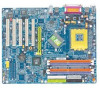
GA-7N400 Pro2 / GA-7N400 / GA-7N400-L AMD Socket A Processor Motherboard USER'S MANUAL AMD Athlon™/ Athlon™ XP / Duron™ Socket A Processor Motherboard Rev. 1002 12ME-7N400P2-1002 7n400pro2_1002_q.p65 1 2003/7/4, ¤U¤È 03:27 - Gigabyte GA-7N400 | User Manual - Page 6
GA-7N400 Pro2 Motherboard Layout 8 GA-7N400 Motherboard Layout 9 GA-7N400-L Motherboard Layout 10 Block Diagram - GA-7N400 Pro2 / GA-7N400 / GA-7N400 23 Chapter 3 BIOS Setup 39 The Main Menu (For example: BIOS Ver. : E2 40 Standard CMOS Features 42 N400 Pro2 / N400 Series Motherboard - Gigabyte GA-7N400 | User Manual - Page 7
Set Supervisor/User Password 63 Save & Exit Setup 64 Exit Without Saving 65 Chapter 4 Technical Reference 67 @BIOS™ Introduction 67 Flash BIOS Method Introduction 68 2- / 4- / 6-Channel Audio Function Introuction 78 Xpress Recovery Introduction 84 Chapter 5 Appendix 89 7n400pro2_1002_q.p65 - Gigabyte GA-7N400 | User Manual - Page 8
Pro2 / N400 Series motherboard CD for motherboard driver & utility The N400 Pro2 / N400 Series user's manual Quick PC Installation Guide GigaRAID manual (j) SATA RAID manual (j) GC-SATA Card (optional) (Manual j For GA-7N400 Pro2 only. k For GA-7N400 only. l For GA-7N400-L only. N400 Pro2 / N400 - Gigabyte GA-7N400 | User Manual - Page 9
24.4cm ATX size form factor, 4 layers PCB — N400 Pro2/N400 Series: GA-7N400 Pro2 / GA-7N400 / GA-7N400-L — Socket A processor for AMD Athlon™ / Athlon™ XP / Duron™ (K7) 128K L1 & 256K/64K L2 cache on die — 400/333/266/200 MHz FSB — Supports 1.4GHz and faster — nVIDIA® nForce™ 2 Ultra 400 Memory/AGP - Gigabyte GA-7N400 | User Manual - Page 10
checking messages during boot-up — Mirroring supports automatic background rebuilds — Features LBA and Extended Interrupt 13 drive translation in controller onboard BIOS to be continued...... j For GA-7N400 Pro 2 only. k For GA-7N400 only. l For GA-7N400-L only. N400 Pro2 / N400 Series Motherboard - Gigabyte GA-7N400 | User Manual - Page 11
Keyboard interface and PS/2 Mouse interface — Licensed AWARD BIOS — Supports Dual BIOS (j) — Supports Face Wizard — Supports Q-Flash — PS/2 Keyboard power on by password — SDRAM, Cards...etc. j For GA-7N400 Pro2 only. k For GA-7N400 only. l For GA-7N400-L only. - 7 - Introduction - Gigabyte GA-7N400 | User Manual - Page 12
CLK_RATIO CPU_FAN RAM_LED ATX PWR_FAN SOCKET A FDD GA-7N400 Pro2 LPT LAN COM B USB DDR1 DDR2 DDR3 DDR4 IDE2 IDE1 Dual Channel DDR AUDIO CLK_SW NB_FAN RTL8110S 2X_DET F_AUDIO CODEC IT8712F CD_IN SUR_CEN BACKUP BIOS MAIN BIOS SPDIF_IO AUX_IN CI IR GAME nVIDIA® nForce™ 2 Ultra - Gigabyte GA-7N400 | User Manual - Page 13
Layout COM A USB KB_MS ATX_12V CLK_RATIO CPU_FAN RAM_LED ATX LPT SOCKET A FDD GA-7N400 DDR1 DDR2 DDR3 DDR4 IDE2 IDE1 Dual Channel DDR COM B USB AUDIO CODEC F_AUDIO CLK_SW 2X_DET IT8712F CD_IN SUR_CEN MAIN BIOS SPDIF_IO AUX_IN CI IR GAME nVIDIA® nForce™ 2 Ultra 400 AGP nVIDIA - Gigabyte GA-7N400 | User Manual - Page 14
ATX_12V CLK_RATIO CPU_FAN RAM_LED ATX SOCKET A FDD GA-7N400-L DDR1 DDR2 DDR3 DDR4 IDE2 IDE1 Dual Channel DDR LPT LAN COM B USB AUDIO CLK_SW nVIDIA® nForce™ 2 Ultra 400 F_AUDIO RTL8100C CODEC 2X_DET IT8712F CD_IN SUR_CEN MAIN BIOS SPDIF_IO AUX_IN CI IR GAME AGP nVIDIA® nForce - Gigabyte GA-7N400 | User Manual - Page 15
BIOS LPC BUS IT8712 TI j TSB43AB23 AC97 Link PCICLK (33MHz) IDE4j IDE3j 2 Serial ATAj AC97 CODEC 6 USB Ports 24 MHz 33 MHz 3 IEEE1394j ATA33/66/100/133 IDE Channels IR Game Port Floppy LPT Port PS/2 KB/Mouse 2 COM Ports MIC LINE-IN LINE-OUT j For GA-7N400 Pro2 only. k For GA-7N400 only - Gigabyte GA-7N400 | User Manual - Page 16
English N400 Pro2 / N400 Series Motherboard - 12 - 7n400pro2_1002_q.p65 12 2003/7/4, ¤U¤È 03:27 - Gigabyte GA-7N400 | User Manual - Page 17
4 Step 5 Congratulations! You have accomplished the hardware installation! Turn on the power supply or connect the power cable to the power outlet. Continue with the BIOS/software installation. - 13 - 7n400pro2_1002_q.p65 13 Hardware Installation Process 2003/7/4, ¤U¤È 03:27 - Gigabyte GA-7N400 | User Manual - Page 18
6 54 321 Default Setting : OFF CLK_SW ON ON OFF CLK_SW ON AUTO OFF 100MHz AUTO : Supports FSB 400/333/266 MHz CPU 100MHz : Fix FSB 200MHz CPU CLK_RATIO O: ON / X : MNote: In order to BIOS can auto detecting when your CPU mutiplier over 18x, please adjust mutiplier swich in CLK_RATIO to " - Gigabyte GA-7N400 | User Manual - Page 19
Step 2: Install the Central Processing Unit (CPU) Before installing the processor, adhere to the following warning: 1. Please make sure the CPU type is supported by the motherboard. 2. If you do not match the CPU socket Pin 1 and CPU cut edge well, it will cause improper installation. Please - Gigabyte GA-7N400 | User Manual - Page 20
fan connector, this completes the installation. Please refer to CPU cooling fan user's manual for more detail installation procedure. 1. Press down the CPU socket lever and finish , than install complete. N400 Pro2 / N400 Series Motherboard - 16 - 7n400pro2_1002_q.p65 16 2003/7/4, ¤U¤È 03:27 - Gigabyte GA-7N400 | User Manual - Page 21
has 4 dual inline memory module (DIMM) sockets. The BIOS will automatically detects memory type and size. To install the memory one direction due to the notch. Memory size can vary between sockets. Notch DDR Support Unbuffered DDR DIMM Sizes type: 64 Mbit (2Mx8x4 banks) 64 Mbit (1Mx16x4 - Gigabyte GA-7N400 | User Manual - Page 22
path from existing SDRAM designs due to its availability, pricing and overall market support. PC2100 DDR memory (DDR266) doubles the data rate through reading and writing value desktop SMA systems. N400 Pro2 / N400 Series Motherboard - 18 - 7n400pro2_1002_q.p65 18 2003/7/4, ¤U¤È 03:27 - Gigabyte GA-7N400 | User Manual - Page 23
Dual Channel DDR: GA-7N400 Pro2 / GA-7N400 / GA-7N400-L support Dual Channel Technology. When Dual Channel Technology is activated, the bandwidth of memory bus will be double the original one, with the fastest speed at 6.4GB/s(DDR400) . GA-7N400 Pro2 / GA-7N400 / GA-7N400-L include 4 DIMM slots - Gigabyte GA-7N400 | User Manual - Page 24
Power on the computer, if necessary, setup BIOS utility of expansion card from BIOS. 8. Install related driver from the operating system. Please carefully pull out installed the 2X_DETwill light up, indicating a non-supported graphics card is inserted. Informing users that system might not boot up normally - Gigabyte GA-7N400 | User Manual - Page 25
USB controller. If your OS does not support USB controller, please contact OS vendor for possible patch or driver upgrade. For more information please contact your OS or device (s) vendors. j For GA-7N400 Pro2 only. l For GA-7N400-L only. - 21 - Hardware Installation Process 7n400pro2_1002_q - Gigabyte GA-7N400 | User Manual - Page 26
(Rear Speaker) Line Out (Front Speaker) MIC In (Center and Subwoofer) After install onboard audio driver, you may connect speaker to Line Out jack, microphone to MIC In jack. Device like CD refer to page 79. N400 Pro2 / N400 Series Motherboard - 22 - 7n400pro2_1002_q.p65 22 2003/7/4, ¤U¤È 03:27 - Gigabyte GA-7N400 | User Manual - Page 27
2X_DET 16) F_AUDIO 17) SUR_CEN 18) SPDIF_IO 19) CD_IN 20) AUX_IN 21) F_USB 22) F1_1394 (j) / F2_1394 (j) 23) IR 24) GAME 25) INFO_LINK 26) CI j For GA-7N400 Pro2 only. k For GA-7N400 only. l For GA-7N400-L only. - 23 - Hardware Installation Process 7n400pro2_1002_q.p65 23 2003/7/4, ¤U¤È 03:27 - Gigabyte GA-7N400 | User Manual - Page 28
GND VCC GND Power Good 5V SB (stand by +5V) +12V 3.3V -12V GND PS_ON(soft on/off) GND GND GND -5V VCC VCC N400 Pro2 / N400 Series Motherboard - 24 - 7n400pro2_1002_q.p65 24 2003/7/4, ¤U¤È 03:27 - Gigabyte GA-7N400 | User Manual - Page 29
of the CPU cooler is essential to prevent the CPU from running under abnormal condition or damaged by overheating. The CPU fan connector supports Max. current up to 600 mA. Pin No. Definition 1 1 GND 2 +12V 3 Sense 4) SYS_FAN (System Fan Connector) This connector allows you to link with - Gigabyte GA-7N400 | User Manual - Page 30
, the chip fan will not work. Sometimes will damage the chip fan. (Usually black cable is GND) Pin No. Definition 1 1 VCC 2 GND j For GA-7N400 Pro2 only. k For GA-7N400 only. l For GA-7N400-L only. N400 Pro2 / N400 Series Motherboard - 26 - 7n400pro2_1002_q.p65 26 2003/7/4, ¤U¤È 03:27 - Gigabyte GA-7N400 | User Manual - Page 31
English 7) FDD (Floppy Connector) Please connect the floppy drive ribbon cables to FDD. It supports 360K, 1.2M, 720K, 1.44M and 2.88M bytes floppy disk types. The red stripe of the ribbon cable must be the same side with the Pin1. - Gigabyte GA-7N400 | User Manual - Page 32
BIOS and install the correct driver to have proper operation. For details, please refer to the SATA RAID manual. 1 1 7 7 SATA0 SATA1 Pin No. 1 2 3 4 5 6 7 Definition GND TXP TXN GND RXN RXP GND Silicon Image Sil3112 chip supports Serial ATA connectors hot plug function. j For GA-7N400 Pro2 - Gigabyte GA-7N400 | User Manual - Page 33
English 11) F_PANEL (2 x 10 pins Connector) Please connect the power LED, PC speaker, reset switch and power switch etc. of your chassis front panel to the F_PANEL connector according to the pin assignment above. Message LED/ Speaker Connector Power/ Soft Power Sleep LED Connector MSG+ MSG- - Gigabyte GA-7N400 | User Manual - Page 34
recommended by the manufacturer. Dispose of used batteries according to the manufacturer's instructions. If you want to erase CMOS... 1. Turn OFF the computer and unplug Definition 1 MPD+ 2 MPD- 3 MPD- N400 Pro2 / N400 Series Motherboard - 30 - 7n400pro2_1002_q.p65 30 2003/7/4, ¤U¤È 03:27 - Gigabyte GA-7N400 | User Manual - Page 35
modules only when AC power cord is disconnected. + _ 15) 2X_DET When an AGP 2X (3.3V) card is installed the 4X_AGP will light up, indicating a non-supported graphics card is inserted. Informing users that system might not boot up normally due to AGP 2X (3.3V) is not - Gigabyte GA-7N400 | User Manual - Page 36
assigment on the MB header. To find out if the chassis you are buying support front audio connector, please contact your dealer. Please note, you can have the SUR OUTL SUR OUTR GND No Pin CENTER_OUT BASS_OUT N400 Pro2 / N400 Series Motherboard - 32 - 7n400pro2_1002_q.p65 32 2003/7/4, ¤U¤È 03:28 - Gigabyte GA-7N400 | User Manual - Page 37
English 18) SPDIF_IO (SPDIF In / Out Connector) The SPDIF output is capable of providing digital audio to external speakers or compressed AC3 data to an external Dolby Digital Decoder. Use this feature only when your stereo system has digital input function. Be careful with the polarity of the - Gigabyte GA-7N400 | User Manual - Page 38
, please contact your local dealer. 2 10 19 Pin No. 1 2 3 4 5 6 7 8 9 10 Definition Power Power USB DxUSB DyUSB Dx+ USB Dy+ GND GND No Pin NC N400 Pro2 / N400 Series Motherboard - 34 - 7n400pro2_1002_q.p65 34 2003/7/4, ¤U¤È 03:28 - Gigabyte GA-7N400 | User Manual - Page 39
English 22) F1_1394 / F2_1394 (Front IEEE1394 Connector) (j) Serial interface standard set by Institute of Electrical and Electronics Engineers, which has features like high speed, highbandwidth and hot plug. Be careful with the polarity of the IEEE1394 connector. Check the pin assignment - Gigabyte GA-7N400 | User Manual - Page 40
English 24) GAME (Game Connector) This connector supports joystick, MIDI keyboard and other relate audio devices. Check the 3 4 5 6 7 8 9 10 Definition SMBCLK VCC SMBDATA GPIO GND GND No Pin NC +12V +12V N400 Pro2 / N400 Series Motherboard - 36 - 7n400pro2_1002_q.p65 36 2003/7/4, ¤U¤È 03:28 - Gigabyte GA-7N400 | User Manual - Page 41
English 26) CI (CASE OPEN) This 2-pin connector allows your system to enable or disable the "Case Open" item in BIOS, if the system case begin remove. Pin No. Definition 1 1 Signal 2 GND - 37 - 7n400pro2_1002_q.p65 37 Hardware Installation Process 2003/7/4, ¤U¤È 03:28 - Gigabyte GA-7N400 | User Manual - Page 42
English N400 Pro2 / N400 Series Motherboard - 38 - 7n400pro2_1002_q.p65 38 2003/7/4, ¤U¤È 03:28 - Gigabyte GA-7N400 | User Manual - Page 43
CMOS value from CMOS, only for Option Page Setup Menu Load the file-safe default CMOS value from BIOS default table Load the Optimized Defaults Dual BIOS/Q-Flash function System Information Save all the CMOS changes, only for Main Menu - 39 - 7n400pro2_1001_b.p65 - Gigabyte GA-7N400 | User Manual - Page 44
widden. l Standard CMOS Features This setup page includes all the items in standard compatible BIOS. l Advanced BIOS Features This setup page includes all the items of Award special enhanced features. N400 Pro2 / N400 Series Motherboard - 40 - 7n400pro2_1001_b.p65 40 2003/7/4, ¤U¤È 03:29 - Gigabyte GA-7N400 | User Manual - Page 45
Setup Save CMOS value settings to CMOS and exit setup. l Exit Without Saving Abandon all CMOS value changes and exit setup. - 41 - 7n400pro2_1001_b.p65 41 BIOS Setup 2003/7/4, ¤U¤È 03:29 - Gigabyte GA-7N400 | User Manual - Page 46
[None] year Sun. to Sat. Drive A Drive B Floppy 3 Mode Support Halt On Base Memory Extended Memory Total Memory [1.44M, 3.5"] [None] [Disabled] [All, >. Week Month Day Year The week, from Sun to Sat, determined by the BIOS and is display only The month, Jan. Through Dec. The day, from 1 - Gigabyte GA-7N400 | User Manual - Page 47
that has been installed in the computer. There are two types: auto type, and manual type. Manual type is user-definable; Auto type which will automatically detect HDD type. Note that 3.5 inch double-sided drive; 2.88M byte capacity. - 43 - 7n400pro2_1001_b.p65 43 BIOS Setup 2003/7/4, ¤U¤È 03:29 - Gigabyte GA-7N400 | User Manual - Page 48
3 Mode Support (for Japan will be prompted. All Errors Whenever the BIOS detects a non-fatal error the system boot Self Test) of the BIOS. Base Memory The POST of the BIOS will determine the amount installed on the motherboard. Extended Memory The BIOS determines how much extended memory is present - Gigabyte GA-7N400 | User Manual - Page 49
+/-/PU/PD: Value F10: Save ESC:Exit F1: General Help F5: Previous Values F6: Fail-Safe Defaults F7: Optimized Defaults Figure 3: Advanced BIOS Features First / Second / Third Boot Device Floppy Select your boot device priority by Floppy. LS120 Select your boot device priority by LS120. HDD - Gigabyte GA-7N400 | User Manual - Page 50
SATA Select your boot device priority by Serial ATA. Boot Up Floppy Seek During POST, BIOS will determine the floppy disk drive installed is 40 or 80 tracks. 360K type is 40 initial display first to AGP. N400 Pro2 / N400 Series Motherboard - 46 - 7n400pro2_1001_b.p65 46 2003/7/4, ¤U¤È 03:29 - Gigabyte GA-7N400 | User Manual - Page 51
) Use over colocked settings for higher performance but with higher risk of instability. Manual Allows full customization of performance options. Incorrect using it may cause your system to 166MHz. Set FSB frequency at 200MHz. - 47 - BIOS Setup 7n400pro2_1001_b.p65 47 2003/7/4, ¤U¤È 03:29 - Gigabyte GA-7N400 | User Manual - Page 52
. AGP Frequency Normal Set the best AGP frequency for system. (Default Value) 50MHz ~ 100MHz Set the AGP frequency manually. Incorrect using it may cause your system broken. For power End-User use only! N400 Pro2 / N400 Series Motherboard - 48 - 7n400pro2_1001_b.p65 48 2003/7/4, ¤U¤È 03:29 - Gigabyte GA-7N400 | User Manual - Page 53
Menu Level u If a hard disk USB Keyboard Support [Disabled] controller card is USB Mouse Support [Disabled] used, set at Disabled AC97 Audio 5: Integrated Peripherals j For GA-7N400 Pro2 only. k For GA-7N400 only. l For GA-7N400-L only. - 49 - BIOS Setup 7n400pro2_1001_b.p65 49 2003/7/4, - Gigabyte GA-7N400 | User Manual - Page 54
Mouse Support. (Default value) AC97 Audio Auto Disabled Auto detect AC'97 audio function. (Default Value) Disable AC'97 audio function. Onboard LAN chip(jl) Enabled Disabled Auto detect onborad LAN function. (Default Value) Disable this function. j For GA-7N400 Pro2 only. k For GA-7N400 only - Gigabyte GA-7N400 | User Manual - Page 55
1 and address is 3E8, using IRQ4. 2E8/IRQ3 Enable onboard Serial port 1 and address is 2E8, using IRQ3. Auto BIOS will automatically setup the port 1 address. j For GA-7N400 Pro2 only. k For GA-7N400 only. l For GA-7N400-L only. - 51 - BIOS Setup 7n400pro2_1001_b.p65 51 2003/7/4, ¤U¤È 03:29 - Gigabyte GA-7N400 | User Manual - Page 56
IRQ4. 2E8/IRQ3 Auto Enable onboard Serial port 2 and address is 2E8, using IRQ3. BIOS will automatically setup the port 2 address. UART Mode Select This item allows you to determine is 3BC, using IRQ7. N400 Pro2 / N400 Series Motherboard - 52 - 7n400pro2_1001_b.p65 52 2003/7/4, ¤U¤È 03:29 - Gigabyte GA-7N400 | User Manual - Page 57
This feature allows you to connect with an advanced printer via the port mode it supports. SPP Using Parallel port as Standard Parallel Port. EPP Using Parallel port as Enhanced Parallel Set Midi Port IRQ to 10. (Default Value) - 53 - 7n400pro2_1001_b.p65 53 BIOS Setup 2003/7/4, ¤U¤È 03:29 - Gigabyte GA-7N400 | User Manual - Page 58
then Power off instantly. (Default value) Delay 4 Sec. Press power button 4 sec. to Power off. Enter suspend if button is pressed less than 4 sec. N400 Pro2 / N400 Series Motherboard - 54 - 7n400pro2_1001_b.p65 54 2003/7/4, ¤U¤È 03:29 - Gigabyte GA-7N400 | User Manual - Page 59
function. (Default value) Mouse Click Double click on PS/2 mouse left button to power on the system. Power On By Keyboard - 55 - 7n400pro2_1001_b.p65 55 BIOS Setup 2003/7/4, ¤U¤È 03:29 - Gigabyte GA-7N400 | User Manual - Page 60
system always in "On" state. When AC-power back to the system, the system will return to the Last state before AC-power off. N400 Pro2 / N400 Series Motherboard - 56 - 7n400pro2_1001_b.p65 56 2003/7/4, ¤U¤È 03:29 - Gigabyte GA-7N400 | User Manual - Page 61
Auto assign IRQ to PCI 4. (Default value) 3,4,5,7,9,10,11,12,14,15 Set IRQ 3,4,5,7,9,10,11,12,14,15 to PCI 4. - 57 - 7n400pro2_1001_b.p65 57 BIOS Setup 2003/7/4, ¤U¤È 03:29 - Gigabyte GA-7N400 | User Manual - Page 62
"Yes". If you want to reset "Case Opened" value, set "Reset Case Open Status" to "Enabled" and save CMOS, your computer will restart. j For GA-7N400 Pro2 only. k For GA-7N400 only. l For GA-7N400-L only. N400 Pro2 / N400 Series Motherboard - 58 - 7n400pro2_1001_b.p65 58 2003/7/4, ¤U¤È 03:29 - Gigabyte GA-7N400 | User Manual - Page 63
at full speed. b. When the CPU temperature is lower than 40 degrees Celsius, CPU fan will run at low speed. Disabled Disable this function. j For GA-7N400 Pro2 only. k For GA-7N400 only. l For GA-7N400-L only. - 59 - BIOS Setup 7n400pro2_1001_b.p65 59 2003/7/4, ¤U¤È 03:29 - Gigabyte GA-7N400 | User Manual - Page 64
Control to +0.2V. Set AGP OverVoltage Control to +0.3V. Incorrect using it may cause your system to fail. For power End-User use only! N400 Pro2 / N400 Series Motherboard - 60 - 7n400pro2_1001_b.p65 60 2003/7/4, ¤U¤È 03:29 - Gigabyte GA-7N400 | User Manual - Page 65
} Standard CMOS Features } Frequency/Voltage Control } Advanced BIOS Features Load Fail-Safe Defaults } Advanced Chipset Features Load } PC Health Status Exit Without Saving ESC: Quit higf: Select Item F8: Dual BIOS / Q-Flash F10: Save & Exit Setup Load Fail-Safe Defaults Figure 10: Load - Gigabyte GA-7N400 | User Manual - Page 66
PC Health Status Exit Without Saving ESC: Quit higf: Select Item F8: Dual BIOS / Q-Flash F10: Save & Exit Setup Load Optimized Defaults Figure 11: field loads the factory defaults for BIOS and Chipset Features which the system automatically detects. N400 Pro2 / N400 Series Motherboard - 62 - Gigabyte GA-7N400 | User Manual - Page 67
Status Exit Without Saving ESC: Quit higf: Select Item F8: Dual BIOS / Q-Flash F10: Save & Exit Setup Change/Set/Disable Password Figure only basic items. If you select "System" at "Password Check" in Advance BIOS Features Menu, you will be prompted for the password every time the system - Gigabyte GA-7N400 | User Manual - Page 68
Standard CMOS Features } Frequency/Voltage Control } Advanced BIOS Features Load Fail-Safe Defaults } Advanced Chipset Features Setup } PC Health Status Exit Without Saving ESC: Quit higf: Select Item F8: Dual BIOS / Q-Flash F10: Save & Exit Setup Save Data to CMOS Figure 13: Save & - Gigabyte GA-7N400 | User Manual - Page 69
Setup Set User Password } PnP/PCI Configurations Save & Exit Setup } PC Health Status Exit Without Saving ESC: Quit higf: Select Item F8: Dual BIOS / Q-Flash F10: Save & Exit Setup Abandon all Data Figure 14: Exit Without Saving Type "Y" will quit the Setup Utility without saving to RTC - Gigabyte GA-7N400 | User Manual - Page 70
English N400 Pro2 / N400 Series Motherboard - 66 - 7n400pro2_1001_b.p65 66 2003/7/4, ¤U¤È 03:29 - Gigabyte GA-7N400 | User Manual - Page 71
! It's free! Now, if you buy a Gigabyte's motherboard, you could find this amazing software in the attached driver CD. But please remember, connected to internet at first, then you could have a internet BIOS update from your Gigabyte @BIOS. - 67 - Technical Reference 7n400pro2_1002_t.p65 67 - Gigabyte GA-7N400 | User Manual - Page 72
Save & Exit Setup } PC Health Status Exit Without Saving ESC: Quit F8: Dual BIOS / Q-Flash higf: Select Item F10: Save & Exit Setup j For GA-7N400 Pro2 only. k For GA-7N400 only. l For GA-7N400-L only. N400 Pro2 / N400 Series Motherboard - 68 - 7n400pro2_1002_t.p65 68 2003/7/4, ¤U¤È 03:30 - Gigabyte GA-7N400 | User Manual - Page 73
Item explanation: • Wide Range Protection: Disable(Default), Enable Status 1: If any failure (ex. Update ESCD failure, checksum error or reset...) occurs in the Main BIOS, just before the Operating System is loaded and after the power is on, and that the Wide Range Protection is set to "Enable", the - Gigabyte GA-7N400 | User Manual - Page 74
Error : Disable(Default), Enable If the BIOS occurs a checksum error or the Main BIOS occurs a WIDE RANGE PROTECTION error and Halt On Error set to Enable, the PC will show messages on the boot screen, and the system will pause and wait for the user's instruction. If Auto Recovery :Disable, it will - Gigabyte GA-7N400 | User Manual - Page 75
: 1.14M DEL: Delete ESC: Return Main Where XXXX.XX is name of the BIOS file. !Press Enter to Run. Are you sure to update BIOS? [Enter] to contiune Or [ESC] ot abort... !Press Enter to Run. !! COPY BIOS Completed -Pass !! Please press any key to continue Congratulation! You have completed the - Gigabyte GA-7N400 | User Manual - Page 76
English Save Main BIOS to Floppy / Save Backup BIOS to Floppy !In the A:drive, insert the floppy disk, then Press Enter to previous item Move to next item Run Reset Power Off N400 Pro2 / N400 Series Motherboard - 72 - 7n400pro2_1002_t.p65 72 2003/7/4, ¤U¤È 03:30 - Gigabyte GA-7N400 | User Manual - Page 77
this innovation. What's DualBIOS™? On GIGABYTE motherboards with DualBIOS there are physically two BIOS chips. For simplicity we'll call one your "Main BIOS" and the other we'll call your "Backup BIOS" (your "hot spare"). If your Main BIOS fails, the Backup BIOS almost automatically takes over on - Gigabyte GA-7N400 | User Manual - Page 78
Recovery" option will guarantee that if either the main BIOS or backup BIOS is corrupted, the DualBIOS™ technology will use the good BIOS and correct the wrong BIOS automatically. 3. DualBIOS™ provides manual recovery for the BIOS. DualBIOS™ technology contains a built-in flash utility, which can - Gigabyte GA-7N400 | User Manual - Page 79
.) A user may override booting from the main system BIOS. The DualBIOS™ utility may be entered to manually change the boot sequence to boot from the backup BIOS. 2. During or after a BIOS upgrade, if DualBIOS™ detects that the main BIOS is corrupt, the backup BIOS will take over the boot-up process - Gigabyte GA-7N400 | User Manual - Page 80
don't have DOS boot disk, we recommend that you used Gigabyte @BIOS™ program to flash BIOS. Press here. 1. Click "@BIOS" item. 2. Click Start/ Programs/ GIGABYTE/ @BIOS. (1) (2) 3.Click "P". Click here 4. Please select @BIOS sever site, then Click "OK". (3) (4) Methods and steps: I. Update - Gigabyte GA-7N400 | User Manual - Page 81
instruction. III. Save BIOS In the very beginning, there is "Save Current BIOS" icon shown in dialog box. It means to save the current BIOS version. IV. Check out supported In method I, if the BIOS file you need cannot be found in @BIOS™ server, please go onto Gigabyte's web site for downloading and - Gigabyte GA-7N400 | User Manual - Page 82
the stereo speakers or earphone to "Line Out". STEP 2 : After installation of the audio driver, you'll find an icon on the taskbar's status area. Click the audio icon "Sound stereo speaker output". Line Out N400 Pro2 / N400 Series Motherboard - 78 - 7n400pro2_1002_t.p65 78 2003/7/4, ¤U¤È 03:30 - Gigabyte GA-7N400 | User Manual - Page 83
4 Channel Analog Audio Output Mode STEP 1 : Connect the front channels to "Line Out", the rear channels to "Line In". STEP 2 : After installation of the audio driver, you'll find an icon on the taskbar's status area. Click the audio icon "Sound Effect" from the windows tray at the bottom of the - Gigabyte GA-7N400 | User Manual - Page 84
channels to "MIC In". MIC In Line Out STEP 2 : After installation of the audio driver, you'll find an icon on the taskbar's status area. Click the audio icon "Sound Disable "Only SURROUND-KIT" and pess "OK". N400 Pro2 / N400 Series Motherboard - 80 - 7n400pro2_1002_t.p65 80 2003/7/4, ¤U¤È 03:30 - Gigabyte GA-7N400 | User Manual - Page 85
channels. It is the best solution if you need 6 channel output, Line In and MIC at the same time. "SURROUND-KIT" is included in the GIGABYTE unique "Audio Combo Kit" as picture. STEP 1 : Insert the "Audio Combo Kit" in the back of the case, and fix it with the screw. STEP - Gigabyte GA-7N400 | User Manual - Page 86
: When the "Environment settings" is "None", the sound would be performed as stereo mode(2 channels output). Please select the other settings for 6 channels output. N400 Pro2 / N400 Series Motherboard - 82 - 7n400pro2_1002_t.p65 82 2003/7/4, ¤U¤È 03:31 - Gigabyte GA-7N400 | User Manual - Page 87
English SPDIF Output Device (Optional Device) A "S/PDIF output" device is available on the motherboard. Cable with rear bracket is provided and could link to the "S/PDIF output" connector (As picture.) For the further linkage to decoder, rear bracket provides coaxial cable and Fiber connecting port - Gigabyte GA-7N400 | User Manual - Page 88
1. It supports FAT16, FAT32, NTFS with IDE hard disk supporting HPA . 4. The supported by Intel 865 / 875 chipset, nVIDIA nForce 2 chipset and SiS 648FX chipset based motherboard from Gigabyte 865PE AGPSet BIOS for 8IPE1000MT BIOS" setting menu and set boot from CD-ROM, then save and exit the BIOS - Gigabyte GA-7N400 | User Manual - Page 89
English b. Xpress Recovery: Xpress Recovery V1.0 (C) Copy Right 2003. GIGABYTE Technilogy CO. , Ltd. 1. Excute Backup Utility 2. Excute Restore Utility 3. Remove Backup Image 4. Exit and Restart 1.Excute Backup Utility: ! Press B to Backup your System or Esc - Gigabyte GA-7N400 | User Manual - Page 90
English N400 Pro2 / N400 Series Motherboard - 86 - 7n400pro2_1002_t.p65 86 2003/7/4, ¤U¤È 03:31 - Gigabyte GA-7N400 | User Manual - Page 91
7n400pro2_1002_t.p65 87 - 87 - Technical Reference 2003/7/4, ¤U¤È 03:31 English - Gigabyte GA-7N400 | User Manual - Page 92
English N400 Pro2 / N400 Series Motherboard - 88 - 7n400pro2_1002_t.p65 88 2003/7/4, ¤U¤È 03:31 - Gigabyte GA-7N400 | User Manual - Page 93
start and show the installation guide. If not, please double click the CD-ROM device icon in "My computer", and execute the setup.exe. INSTALL CHIPSET DRIVER This page shows the drivers that need to be installed for the system. Click each item to install the driver manually or switch to the to - Gigabyte GA-7N400 | User Manual - Page 94
Service Pack, it will show a question mark "?" in "Universal Serial Bus controller" under "Device Manager". Please remove the question mark and restart the system (System will auto-detect the right USB2.0 driver). j For GA-7N400 Pro2 only. k For GA-7N400 only. l For GA-7N400-L only. N400 Pro2 - Gigabyte GA-7N400 | User Manual - Page 95
acceleration that support for operating system to achieve better 3D performence. n Silicon Image SATA RAID Utility (j) Serial-ATA RAID utility for Silicon Image Sil3112 n GigaRAID Utility (j) RAID utility for GigaRAID IT8212 j For GA-7N400 Pro2 only. k For GA-7N400 only. l For GA-7N400-L only. - 91 - Gigabyte GA-7N400 | User Manual - Page 96
INFORMATION This page list the contects of softwares and drivers in this CD title. HARDWARE INFORMATION This page lists all device you have for this motherboard. CONTACT US Please see the last page for details. N400 Pro2 / N400 Series Motherboard - 92 - 7n400pro2_1002_a.p65 92 2003/7/4, ¤U¤È 03 - Gigabyte GA-7N400 | User Manual - Page 97
allows users to change the boot-up logo with picture from Gigabyte Logo Gallery on web site or other compatible picture you have. How and combine the compatible picture you prefer into BIOS. And not only this, Face-Wizard™ also helps user to update BIOS in windows mode. What's benefit for using - Gigabyte GA-7N400 | User Manual - Page 98
before installing drivers. You also need to go through some rather different steps in the installation process. Therefore, we suggest that you refer to the installation steps in the RAID manual at our website. (Please download it at http://tw.giga-byte.com/support/user_pdf/raid_manual.pdf) Question - Gigabyte GA-7N400 | User Manual - Page 99
card? Answer: Gigabyte motherboards will auto-detect the external VGA card after it is plugged in, so you don't need to change any setting manually to disable problems. However, they are only for reference purposes. The situations might differ from case to case. gAMI BIOS Beep Codes g AWARD BIOS - Gigabyte GA-7N400 | User Manual - Page 100
If you encounter any trouble during boot up, please follow the troubleshooting procedures. START Turn off the power and unplug the AC power cable, . Then plug in ATX power cable and turn on the system. A N400 Pro2 / N400 Series Motherboard - 96 - 7n400pro2_1002_a.p65 96 2003/7/4, ¤U¤È 03:32 - Gigabyte GA-7N400 | User Manual - Page 101
working properly. Yes Press to enter BIOS setup. Choose "Load Optimized Defaults" and save problem, please contact with your local retailer or national distributor for help. Or, you could submit your question to the service mail via Gigabyte website technical support zone (http://www.gigabyte - Gigabyte GA-7N400 | User Manual - Page 102
: BIOS version: O.S./A.S.: Hardware Mfs. Model name Size: Configuration CPU Memory Brand Video Card Audio Card HDD CD-ROM / DVD-ROM Modem Network AMR / CNR Keyboard Mouse Power supply Other Device Phone No.: PCB revision: Driver/Utility: Problem Description: & N400 Pro2 - Gigabyte GA-7N400 | User Manual - Page 103
English Acronyms Acronyms ACPI APM AGP AMR ACR BIOS CPU CMOS CRIMM CNR DMA DMI DIMM DRM DRAM DDR ECP ESCD ECC EMC EPP ESD FDD FSB HDD IDE IRQ Meaning Advanced Configuration and - Gigabyte GA-7N400 | User Manual - Page 104
PCI A.G.P. Controller Power-On Self Test Peripheral Component Interconnect Rambus in-line Memory Module Special Circumstance Instructions Single Edge Contact Cartridge Static Random Access Memory N400 Pro2 / N400 Series Motherboard - 100 - 7n400pro2_1002_a.p65 100 2003/7/4, ¤U¤È 03:32 - Gigabyte GA-7N400 | User Manual - Page 105
7n400pro2_1002_a.p65 - 101 - 101 Appendix 2003/7/4, ¤U¤È 03:32 English - Gigabyte GA-7N400 | User Manual - Page 106
English N400 Pro2 / N400 Series Motherboard - 102 - 7n400pro2_1002_a.p65 102 2003/7/4, ¤U¤È 03:32 - Gigabyte GA-7N400 | User Manual - Page 107
7n400pro2_1002_a.p65 - 103 - 103 Appendix 2003/7/4, ¤U¤È 03:32 English - Gigabyte GA-7N400 | User Manual - Page 108
English N400 Pro2 / N400 Series Motherboard - 104 - 7n400pro2_1002_a.p65 104 2003/7/4, ¤U¤È 03:32 - Gigabyte GA-7N400 | User Manual - Page 109
7n400pro2_1002_a.p65 - 105 - 105 Appendix 2003/7/4, ¤U¤È 03:32 English - Gigabyte GA-7N400 | User Manual - Page 110
English N400 Pro2 / N400 Series Motherboard - 106 - 7n400pro2_1002_a.p65 106 2003/7/4, ¤U¤È 03:32 - Gigabyte GA-7N400 | User Manual - Page 111
7n400pro2_1002_a.p65 - 107 - 107 Appendix 2003/7/4, ¤U¤È 03:32 English - Gigabyte GA-7N400 | User Manual - Page 112
-428329 (Tech.) E-mail:[email protected] Web Address: www.gigabyte.de — JAPAN/Nippon Giga-Byte Corporation Web Address: www.gigabyte.co.jp — U.K G.B.T. gigabyte.com.cn E-mail:[email protected] Chengdu Office Tel: 86-28-85236930 Fax: 86-28-85256822 Web Address: www.gigabyte.com.cn N400 Pro2
-
 1
1 -
 2
2 -
 3
3 -
 4
4 -
 5
5 -
 6
6 -
 7
7 -
8
-
9
-
10
-
11
-
12
-
13
-
14
-
15
-
16
-
17
-
18
-
19
-
20
-
21
-
22
-
23
-
24
-
25
-
26
-
27
-
28
-
29
-
30
-
31
-
32
-
33
-
34
-
35
-
36
-
37
-
38
-
39
-
40
-
41
-
42
-
43
-
44
-
45
-
46
-
47
-
48
-
49
-
50
-
51
-
52
-
53
-
54
-
55
-
56
-
57
-
58
-
59
-
60
-
61
-
62
-
63
-
64
-
65
-
66
-
67
-
68
-
69
-
70
-
71
-
72
-
73
-
74
-
75
-
76
-
77
-
78
-
79
-
80
-
81
-
82
-
83
-
84
-
85
-
86
-
87
-
88
-
89
-
90
-
91
-
92
-
93
-
94
-
95
-
96
-
97
-
98
-
99
-
100
-
101
-
102
-
103
-
104
-
105
-
106
-
107
-
108
-
109
-
110
-
111
-
112
 |
 |
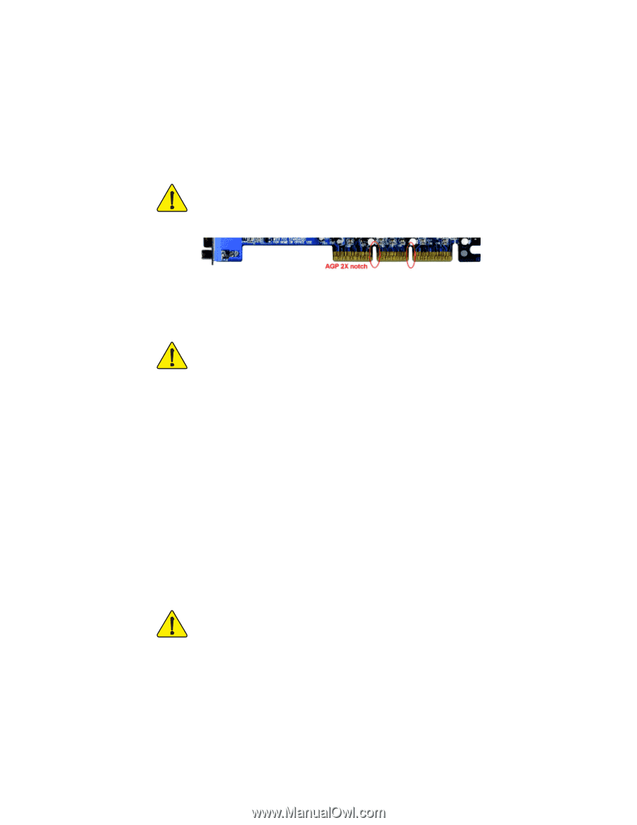
When you installing AGP card, please make sure the following notice
is fully understood and practiced.
If your AGP card has "AGP 4X/8X
(1.5V) notch"(show below), please make sure your AGP card is AGP
4X/8X.
Caution: AGP 2X card is not supported by nVIDIA
®
nForce
™
2 Ultra 400.
You might experience system unable to boot up normally. Please
insert an AGP Pro 4X/8X card.
Example 1: Diamond Vipper V770 golden finger is compatible with 2X/4X
mode AGP slot. It can be switched between AGP 2X(3.3V) or 4X(1.5V) mode
by adjusting the jumper. The factory default for this card is 2X(3.3V). The
GA-7N400 Pro2 / GA-7N400 / GA-7N400-L (or any AGP 4X/8X only)
motherboards might not function properly, if you install this card without
switching the jumper to 4X(1.5V) mode in it.
Example 2: Some ATi Rage 128 Pro graphics cards made by "Power Color",
the graphics card manufacturer & some SiS 305 cards, their golden finger is
compatible with 2X(3.3V) / 4X(1.5V) mode AGP slot, but they support
2X(3.3V) only. The GA-7N400 Pro2 / GA-7N400 / GA-7N400-L (or any AGP
4X/8X only) motherboards might not function properly, If you install this card
in it.
Note : Although Gigabyte's AG32S(G) graphics card is based on ATi Rage
128 Pro chip, the design of AG32S(G) is compliance with AGP 4X(1.5V)
specification. Therefore, AG32S(G) will work fine with nVIDIA
®
nForce2 Ultra
400 based motherboards.
Before you install PCI cards, please remove the Dual BIOS label from PCI
slots if there is one.
AGP 4X/8X notch
7n400Pro2_1002_f.p65
2003/7/4, ¤U¤È 03:21
1