Gigabyte GA-7N400 User Manual - Page 6

English - pro2 bios

Page 6 highlights

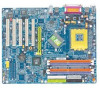
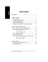
English Table of Content Item Checklist 4 Chapter 1 Introduction 5 Features Summary 5 GA-7N400 Pro2 Motherboard Layout 8 GA-7N400 Motherboard Layout 9 GA-7N400-L Motherboard Layout 10 Block Diagram - GA-7N400 Pro2 / GA-7N400 / GA-7N400-L 11 Chapter 2 Hardware Installation Process 13 Step 1: Set System Jumper (CLK_SW)&(CLK_RATIO 14 Step 2: Install the Central Processing Unit (CPU 15 Step 2-1: CPU Installation 15 Step 2-2: CPU Cooling Fan Installation 16 Step 3: Install Memory Modules 17 Step 4: Install expansion cards 20 Step 5: Connect ribbon cables, cabinet wires and power supply 21 Step 5-1: I/O Back Panel Introduction 21 Step 5-2: Connectors Introduction 23 Chapter 3 BIOS Setup 39 The Main Menu (For example: BIOS Ver. : E2 40 Standard CMOS Features 42 N400 Pro2 / N400 Series Motherboard - 2 - 7n400pro2_1002_q.p65 2 2003/7/4, ¤U¤È 03:27

  • 1
  • 2
  • 3
  • 4
  • 5
  • 6
  • 7
  • 8
  • 9
  • 10
  • 11
  • 12
  • 13
  • 14
  • 15
  • 16
  • 17
  • 18
  • 19
  • 20
  • 21
  • 22
  • 23
  • 24
  • 25
  • 26
  • 27
  • 28
  • 29
  • 30
  • 31
  • 32
  • 33
  • 34
  • 35
  • 36
  • 37
  • 38
  • 39
  • 40
  • 41
  • 42
  • 43
  • 44
  • 45
  • 46
  • 47
  • 48
  • 49
  • 50
  • 51
  • 52
  • 53
  • 54
  • 55
  • 56
  • 57
  • 58
  • 59
  • 60
  • 61
  • 62
  • 63
  • 64
  • 65
  • 66
  • 67
  • 68
  • 69
  • 70
  • 71
  • 72
  • 73
  • 74
  • 75
  • 76
  • 77
  • 78
  • 79
  • 80
  • 81
  • 82
  • 83
  • 84
  • 85
  • 86
  • 87
  • 88
  • 89
  • 90
  • 91
  • 92
  • 93
  • 94
  • 95
  • 96
  • 97
  • 98
  • 99
  • 100
  • 101
  • 102
  • 103
  • 104
  • 105
  • 106
  • 107
  • 108
  • 109
  • 110
  • 111
  • 112

- 2 -
N400 Pro2 / N400 Series Motherboard
English
T
able of Content
Item Checklist
.........................................................................................
4
Chapter 1
Introduction
............................................................................
5
Features Summary
......................................................................................
5
GA-7N400 Pro2 Motherboard Layout
.........................................................
8
GA-7N400 Motherboard Layout
..................................................................
9
GA-7N400-L Motherboard Layout
.............................................................
10
Block Diagram - GA-7N400 Pro2
/ GA-7N400 / GA-7N400-L
.................
11
Chapter 2
Hardware Installation Process
.............................................
13
Step 1: Set System Jumper (CLK_SW)&(CLK_RATIO)
............................
14
Step 2: Install the Central Processing Unit (CPU)
.....................................
15
Step 2-1: CPU Installation
..............................................................................................
15
Step 2-2: CPU Cooling Fan Installation
........................................................................
16
Step 3: Install Memory Modules
................................................................
17
Step 4: Install expansion cards
.................................................................
20
Step 5: Connect ribbon cables, cabinet wires and power supply
............
21
Step 5-1: I/O Back Panel Introduction
...........................................................................
21
Step 5-2: Connectors Introduction
.................................................................................
23
Chapter 3
BIOS Setup
.........................................................................
39
The Main Menu (For example: BIOS Ver. : E2)
........................................
40
Standard CMOS Features
.........................................................................
42
7n400pro2_1002_q.p65
2003/7/4, ¤U¤È 03:27
2