Gigabyte GA-8I925XC-G Manual - Page 18
Connectors Introduction
 |
View all Gigabyte GA-8I925XC-G manuals
Add to My Manuals
Save this manual to your list of manuals |
Page 18 highlights
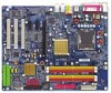
English Side Speaker Out Connect the side surround speakers to this connector. You can use audio software to configure 2-/4-/6-/8-channel audio functioning. 1-7 Connectors Introduction 1 3 10 5 2 8 6 13 14 19 18 7 4 12 11 9 17 16 15 1) ATX_12V 11) PWR_LED 2) ATX (Power Connector) 12) F_PANEL 3) CPU_FAN 13) AZALIA_FP 4) SYS_FAN 14) CD_IN 5) PWR_FAN 15) F_USB1 / F_USB2 6) NB_FAN 16) F1_1394 / F2_1394 7) FDD 17) IR 8) IDE 18) CLR_CMOS 9) IDE2 / IDE3 19) BATTERY 10) SATA0_SB/SATA1_SB/SATA2_SB/SATA3_SB GA-8I925XE-G / GA-8I925XC-G Motherboard - 18 -
-
 1
1 -
2
-
3
-
4
-
5
-
6
-
7
-
8
-
9
-
10
-
11
-
12
-
 13
13 -
 14
14 -
 15
15 -
 16
16 -
 17
17 -
 18
18 -
 19
19 -
 20
20 -
 21
21 -
 22
22 -
 23
23 -
24
-
25
-
26
-
27
-
28
-
29
-
30
-
31
-
32
-
33
-
34
-
35
-
36
-
37
-
38
-
39
-
40
-
41
-
42
-
43
-
44
-
45
-
46
-
47
-
48
-
49
-
50
-
51
-
52
-
53
-
54
-
55
-
56
-
57
-
58
-
59
-
60
-
61
-
62
-
63
-
64
-
65
-
66
-
67
-
68
-
69
-
70
-
71
-
72
-
73
-
74
-
75
-
76
-
77
-
78
-
79
-
80
-
81
-
82
-
83
-
84
-
85
-
86
-
87
-
88
 |
 |

GA-8I925XE-G / GA-8I925XC-G Motherboard
- 18 -
English
1-7
Connectors Introduction
1)
ATX_12V
2)
ATX (Power Connector)
3)
CPU_FAN
4)
SYS_FAN
5)
PWR_FAN
6)
NB_FAN
7)
FDD
8)
IDE
9)
IDE2 / IDE3
10)
SATA0_SB/SATA1_SB/SATA2_SB/SATA3_SB
11)
PWR_LED
12)
F_PANEL
13)
AZALIA_FP
14)
CD_IN
15)
F_USB1 / F_USB2
16)
F1_1394 / F2_1394
17)
IR
18)
CLR_CMOS
19)
BATTERY
Side Speaker Out
Connect the side surround speakers to this connector.
You can use audio software to configure 2-/4-/6-/8-channel audio functioning.
1
3
4
19
16
8
2
7
13
11
9
17
15
5
6
12
14
18
10