Gigabyte GA-A75M-S2V User Manual - Page 17
CPU_FAN/SYS_FAN Fan Headers, SATA3_0/1/2/3/4/5 SATA 6Gb/s Connectors, Controlled by AMD A75 Chipset
 |
View all Gigabyte GA-A75M-S2V manuals
Add to My Manuals
Save this manual to your list of manuals |
Page 17 highlights
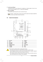
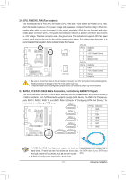
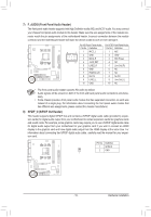
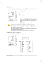
3/4) CPU_FAN/SYS_FAN (Fan Headers) The motherboard has a 4-pin APU fan header (CPU_FAN) and a 4-pin system fan header (SYS_FAN). Each fan header supplies a +12V power voltage and possesses a foolproof insertion design. When connecting a fan cable, be sure to connect it in the correct orientation. Most fans are designed with colorcoded power connector wires. A red power connector wire indicates a positive connection and requires a +12V voltage. The black connector wire is the ground wire. The motherboard supports APU fan speed control, which requires the use of a fan with fan speed control design. For optimum heat dissipation, it is recommended that a system fan be installed inside the chassis. CPU_FAN: Pin No. Definition 1 CPU_FAN 1 GND 2 +12V /Speed Control 3 Sense 4 Speed Control SYS_FAN: Pin No. DefiDnEitBioUnG 1 GNDPORT 1 SYS_FAN 2 +12V /Speed Control DEBUG 3 SenPsOeRT 4 Reserve DEBUG •• Be sure to connect fan cables to the fan headers to prevent your APU and system PfrOomRToverheating. Over- heating may result in damage to the APU or the system may hang. •• These fan headers are not configuration jumper blocks. Do not place a jumper cap oDPnOEtBRhUTeGheaders. 5) SATA3_0/1/2/3/4/5 (SATA 6Gb/s Connectors, Controlled byDAEBMUGD A75 CDhEiBpUsGet) PORT PORT The SATA connectors conform to SATA 6Gb/s standard and are compatible with SATA 3Gb/s and SATA 1.5Gb/s standards. Each SATA connector supports a single SATA device. The AMD A75 Chipset sup- ports RAID 0, RAID 1, RAID 10, and JBOD. Refer to Chapter 4, "Configuring SATA Hard Drive(s)," for instructions on configuring a RAID array. SATA3_5 1 7 SATA3_4 1 7 SATA3_3 1 7 Pin No. 1 2 3 4 5 Definition GND TXP TXN GND RXN SATA3_2 6 RXP 1 7 7 GND SATA3_0 SATA3_1 1 7 • A RAID 0 or RAID 1 configuration requires at least two Please connect the L-shaped end of hard drives. If more than two hard drives are to be used, the SATA cable to your SATA hard the total number of hard drives must be an even number. drive. • A RAID 10 configuration requires four hard drives. - 17 - Hardware Installation
-
 1
1 -
2
-
3
-
4
-
5
-
6
-
7
-
8
-
9
-
10
-
11
-
 12
12 -
 13
13 -
 14
14 -
 15
15 -
 16
16 -
 17
17 -
 18
18 -
 19
19 -
 20
20 -
 21
21 -
 22
22 -
23
-
24
-
25
-
26
-
27
-
28
-
29
-
30
-
31
-
32
-
33
-
34
-
35
-
36
-
37
-
38
-
39
-
40
-
41
-
42
-
43
-
44
 |
 |
