Gigabyte GA-G1975X Manual
Gigabyte GA-G1975X Manual
 |
View all Gigabyte GA-G1975X manuals
Add to My Manuals
Save this manual to your list of manuals |
Gigabyte GA-G1975X manual content summary:
- Gigabyte GA-G1975X | Manual - Page 1
GA-G1975X Intel® Pentium® Processor Extreme Edition Intel® Pentium® D / Pentium® 4 LGA775 Processor Motherboard User's Manual Rev. 1005 12ME-G1975X-1005R * The WEEE marking on the product indicates this product must not be disposed of with user's other household waste and must be handed over to a - Gigabyte GA-G1975X | Manual - Page 2
Motherboard GA-G1975X Dec. 16, 2005 Motherboard GA-G1975X Dec. 16, 2005 - Gigabyte GA-G1975X | Manual - Page 3
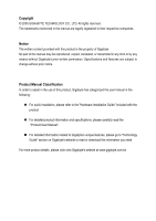
product information and specifications, please carefully read the "Product User Manual". „ For detailed information related to Gigabyte's unique features, please go to "Technology Guide" section on Gigabyte's website to read or download the information you need. For more product details, please - Gigabyte GA-G1975X | Manual - Page 4
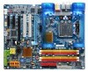
GA-G1975X Motherboard Layout 7 Block Diagram ...8 Chapter 1 Hardware Installation 9 1-1 Considerations Prior to Installation 9 1-2 Feature Summary 10 1-3 Installation of the CPU and Heatsink 13 1-3-1 Installation of the CPU 13 1-3-2 Installation of the Heatsink 14 1-4 Installation of Memory - Gigabyte GA-G1975X | Manual - Page 5
4-1-2 Xpress Recovery2 Introduction 65 4-1-3 Flash BIOS Method Introduction 67 4-1-4 Configuring SATA Hard Drive(s) (Controller: Intel ICH7R 79 4-1-5 2- / 4- / 5.1- / 6.1- / 7.1- Channel Audio Function Introduction 90 4-1-6 DTS Introduction 96 4-2 Troubleshooting 103 4-3 POST Error Code 104 - Gigabyte GA-G1975X | Manual - Page 6
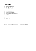
Item Checklist IDE Cable x 2 & FDD Cable x 1 Serial ATAII Cable x 4 Serial ATA Power Cable x 2 SATA + Serial ATA Power Cable x 1 2 Ports USB 2.0 Cable x 2 8-Channel Audio Combo kit x 1 2 Ports USB 2.0 + 2 Ports 1394 Cable x 1 I/O Shield DGBR2 Card bracket External Serial ATA Card DGBR2 Card * The - Gigabyte GA-G1975X | Manual - Page 7
GA-G1975X Motherboard Layout KB_MS AUDIO LGA775 CPU_FAN ATX_12V_2X4 ATX PWR_FAN USB F_AUDIO LAN Intel® 975X CD_IN Broadcom 5789 PCIE_16_1 PCIE1 SUR_CEN PCIE2 PCIE_16_2 PCIE_4_1 SPDIF_IO PCIE_4_2 COMA PW1 PCIE_12V FDD IDE1 DDRII1 DDRII2 DDRII3 DDRII4 CI Intel® ICH7R MAIN BIOS - Gigabyte GA-G1975X | Manual - Page 8
1) DDR II memory can be overclocked to 888MHz (must be used with a 1066MHz FSB processor) through overclocking in BIOS. Go to GIGABYTE's website for more information about the supported DDR II memory modules for this feature. (Note 2) To use a DDR II 667 memory module on the motherboard, you must - Gigabyte GA-G1975X | Manual - Page 9
steps or have a problem related to the use of the product, please consult a certified computer technician. Instances of Non-Warranty 1. Damage due to natural disaster, accident or human cause. 2. Damage as a result of violating the conditions recommended in the user manual. 3. Damage due to - Gigabyte GA-G1975X | Manual - Page 10
Feature Summary CPU Front Side Bus Chipset LAN Audio IEEE 1394 Storage O.S Support Memory Expanstion Slots Š Supports LGA775 Intel® Pentium® Processor Extreme Edition/ Pentium® D / Pentium® 4 (Note 1) Š L2 cache varies with CPU Š Supports 1066/800MHz FSB Š Northbridge: Intel® 975X Express Chipset - Gigabyte GA-G1975X | Manual - Page 11
fan speed detection Š CPU warning temperature Š CPU / System / Power fan failure warning Š CPU smart fan control BIOS Š 2 4M bit flash ROM Š Use of licensed AWARD BIOS Š Supports DualBIOS/Multilanguage BIOS Additional Features Š Supports @BIOS Š Supports Download Center Š Supports Q-Flash - Gigabyte GA-G1975X | Manual - Page 12
Go to GIGABYTE's website for more information about the supported DDR II memory modules for this feature. (Note 4) To use a DDR II 667 memory module on the motherboard, you must install an 800/1066MHz FSB processor. (Note 5) EasyTune functions may vary depending on different motherboards. GA-G1975X - Gigabyte GA-G1975X | Manual - Page 13
the motherboard supports the CPU. 2. Please take note of the one indented corner of the CPU. If you install the CPU in the wrong direction, the CPU will - CPU: An Intel® Pentium 4 Processor with HT Technology - Chipset: An Intel® Chipset that supports HT Technology - BIOS: A BIOS that supports HT - Gigabyte GA-G1975X | Manual - Page 14
instruction is only for Intel boxed fan) Fig. 3 Place the heatsink atop the CPU and make sure the push pins aim to the pin hole on the motherboard. installation instructions, please refer to the heatsink installation section of the user manual) Fig. 5 Please check the back of motherboard after - Gigabyte GA-G1975X | Manual - Page 15
in only one direction. If you are unable to insert the module, please switch the direction. The motherboard supports DDR II memory modules, whereby BIOS will automatically detect memory capacity and specifications. Memory modules are designed so that they can be inserted only in one direction. The - Gigabyte GA-G1975X | Manual - Page 16
them into DIMM sockets of the same color. The following is a Dual Channel Memory configuration table: (DS: Double Side, SS: Single Side) 2 memory modules 4 memory modules DDR II 1 DS/SS X DS/SS DDR II 2 X DS/SS DS/SS DDR II 3 DS/SS X DS/SS DDR II 4 X DS/SS DS/SS GA-G1975X Motherboard - 16 - - Gigabyte GA-G1975X | Manual - Page 17
related expansion card's instruction document before install the expansion card firmly into expansion slot in motherboard. 4. Be sure the metal contacts on setup BIOS utility of expansion card from BIOS. 8. Install related driver from . To release an installed card, users can also press the latch on - Gigabyte GA-G1975X | Manual - Page 18
XP operating system. With Multi View technology from GIGABYTE, Dual Graphic enabled motherboards offer multiple display support on up to eight separate monitors. This improves the capabilities and productivity of the user by allowing them to spread multiple windows over eight monitors and view them - Gigabyte GA-G1975X | Manual - Page 19
To enable CrossFireTM technology on the motherboard, you need one ATI CrossFireTM II. Supported Operating Systems: Only Windows XP operating system is currrently supported by the an adapter. Graphics Card Driver Setting: Step 1: After installing graphics card driver in operating system, access the - Gigabyte GA-G1975X | Manual - Page 20
. If your OS does not support USB controller, please contact OS vendor for possible patch or driver upgrade. For more information please contact your OS or device(s) vendors. You can use audio software to configure 2-/4-/5.1-/6.1-/7.1-channel audio functioning. GA-G1975X Motherboard - 20 - - Gigabyte GA-G1975X | Manual - Page 21
English 1-8 Connectors Introduction 3 41 2 6 7 13 8 12 19 10 5 21 9 14 11 18 8 20 17 22 16 15 1) ATX_12V_2X4 2) ATX (Power Connector) 3) PCIE_12V 4) CPU_FAN 5) SYS_FAN 6) PWR_FAN 7) FDD 8) IDE1 / IDE2 9) SATAII0_1 / SATAII2_3 10) BATTERY 11) F_PANEL 12) F_AUDIO 13) CD_IN 14) - Gigabyte GA-G1975X | Manual - Page 22
pin ATX 12V power connector, please remove the small cover on the power connector on the motherboard before plugging in the power cord ; otherwise, please do not remove it. 5 8 Pin No. Definition 1 GND 2 GND 1 4 3 GND 4 GND 5 +12V 6 +12V 7 +12V 8 +12V 13 1 24 12 GA-G1975X - Gigabyte GA-G1975X | Manual - Page 23
to the cooler to prevent system overheating and failure. Caution! Please remember to connect the power to the CPU fan to prevent CPU overheating and failure. 1 CPU_FAN 1 Pin No. 1 2 3 4 Definition GND +12V Sense Speed Control (Only for CPU_FAN) SYS_FAN / PWR_FAN - 23 - Hardware Installation - Gigabyte GA-G1975X | Manual - Page 24
the cable connects to the FDD drive. The types of FDD drives supported are: 360KB, 720KB, 1.2MB, 1.44MB and 2.88MB. Please connect instructions located on the IDE device).To ensure that an IDE CD-ROM drive can work properly, please attach it to the IDE 1 connector. IDE1 40 39 GA-G1975X Motherboard - Gigabyte GA-G1975X | Manual - Page 25
can provide up to 300MB/s transfer rate. Please refer to the BIOS setting for the Serial ATA and install the proper driver in order to work properly. 1 7 7 1 Pin No the manufacturer. Dispose of used batteries according to the manufacturer's instructions. If you want to erase CMOS... 1. Turn OFF - Gigabyte GA-G1975X | Manual - Page 26
1: Power Pin 2- Pin 3: NC Pin 4: Data(-) Open: Normal Close: Reset Hardware System Open: Normal Close: Power On/Off Pin 1: LED anode(+) Pin 2: LED cathode(-) NC GA-G1975X Motherboard - 26 - - Gigabyte GA-G1975X | Manual - Page 27
English 12) F_AUDIO (Front Audio Connector) If you wish to use the front audio function, connect the front panel audio module to this connector. Check the pin assignments carefully while you connect the front panel audio module. Incorrect connection between the module and connector will make the - Gigabyte GA-G1975X | Manual - Page 28
GREEN_USB connector provides no standby power when system is off and it does not support USB device to wake up from S3 mode. Users who wish to shut down the standby power(note) for their USB devices (example: optical mouses) will not light on during system power-off. GA-G1975X Motherboard - 28 - - Gigabyte GA-G1975X | Manual - Page 29
Institute of Electrical and Electronics Engineers, which has features like high speed, highbandwidth and hot plug. Be careful with the polarity of connect the external device cable. Please contact your nearest dealer for the optional GIGABYTE external device. 26 15 Pin No. 1 2 3 4 5 6 Definition - Gigabyte GA-G1975X | Manual - Page 30
Intrusion, Case Open) This 2-pin connector allows your system to detect if the chassis cover is removed. You can check the "Case Opened" status in BIOS Setup. Pin No. Definition 1 Signal 2 GND 1 GA-G1975X Motherboard - 30 - - Gigabyte GA-G1975X | Manual - Page 31
English 20) COMA (COMA Connector) Be careful with the polarity of the COMA connector. Check the pin assignment carefully while you connect the COMA cable, incorrect connection between the cable and connector will make the device unable to work or even damage it. For optional COMA cable, please - Gigabyte GA-G1975X | Manual - Page 32
PW1 / PW2 C.R.S. (CMOS Reload Switch) allows user to clear the CMOS and reboot the system simultaneously. C.R.S. provides convenient default settings retrieve and jumper-free CMOS reload. PW1(Red) PW2(Blue) Definition PW1 Clear CMOS + Power On PW2 Power On / Off GA-G1975X Motherboard - 32 - - Gigabyte GA-G1975X | Manual - Page 33
- 33 - Hardware Installation English - Gigabyte GA-G1975X | Manual - Page 34
English GA-G1975X Motherboard - 34 - - Gigabyte GA-G1975X | Manual - Page 35
BIOS, either GIGABYTE's Q-Flash or @BIOS utility can be used. Q-Flash allows the user to quickly and easily update or backup BIOS without entering the operating system. @BIOS is a Windows-based utility that does not require users to boot to DOS before upgrading BIOS but directly download and update - Gigabyte GA-G1975X | Manual - Page 36
Defaults in the BIOS when somehow the system works not stable as usual. This action makes the system reset to the default for stability. The BIOS Setup menus described in this chapter are for reference only and may differ from the exact settings for your motherboard. GA-G1975X Motherboard - 36 - - Gigabyte GA-G1975X | Manual - Page 37
in standard compatible BIOS. „ Advanced BIOS Features This setup Temperature, voltage, fan, speed. „ MB Intelligent Tweaker(M.I.T.) This setup page is control CPU clock and frequency the system and Setup, or just to Setup. „ Set User Password Change, set, or disable password. It allows you to - Gigabyte GA-G1975X | Manual - Page 38
Drive B Floppy 3 Mode Support Halt On [None] [ Memory Extended Memory Total Memory 640K F7: Optimized Defaults Date The date format is , , , . Week Month The week, from Sun to Sat, determined by the BIOS and is display Manual User can manually GA-G1975X Motherboard - 38 - - Gigabyte GA-G1975X | Manual - Page 39
88M, 3.5" 3.5 inch double-sided drive; 2.88M byte capacity. Floppy 3 Mode Support (for Japan Area) Disabled Drive A Normal Floppy Drive. (Default value) Drive may be detected and you will be prompted. All Errors Whenever the BIOS detects a non-fatal error the system will be stopped. All, But - Gigabyte GA-G1975X | Manual - Page 40
more memory installed on the motherboard. Extended Memory The BIOS determines how much extended memory is present during the POST. This is the amount of memory located above 1 MB in the CPU's memory address map. Total Memory This item displays the memory size that used. GA-G1975X Motherboard - 40 - Gigabyte GA-G1975X | Manual - Page 41
-CDROM Select your boot device priority by USB-CDROM. USB-HDD Select your boot device priority by USB-HDD. LAN Select your boot device priority by LAN. Disabled Disable this function. (Note) This item will show up when you install a processor that supports this function. - 41 - BIOS Setup - Gigabyte GA-G1975X | Manual - Page 42
, 1.2M and 1.44M are all 80 tracks. Disabled BIOS will not search for the type of floppy disk drive by processors mode supported. (Default value) Disabled Disables CPU Hyper Threading. (Note) This item will show up when you install a processor that supports this function. GA-G1975X Motherboard - Gigabyte GA-G1975X | Manual - Page 43
to 3 when use older OS like NT4. Disables CPUID Limit for windows XP.(Default value) No-Execute Memory Protect (Note) Enabled Enable No-Execute Memory Protect function.(Default value) Disabled Disable No-Execute Memory Protect function. CPU Enhanced Halt (C1E) (Note) Enabled Disabled Enable - Gigabyte GA-G1975X | Manual - Page 44
PCI IDE SATA RAID/AHCI Mode On-Chip SATA Mode x PATA IDE Set to SATA Port 0/2 Set to SATA Port 1/3 Set to USB Controller USB 2.0 Controller USB Keyboard Support USB Mouse Support Legacy USB storage detect Onboard H/W Sound Onboard H/W 1394 Onboard H/W GigaATA Onboard H/W LAN OnBoard LAN Boot ROM - Gigabyte GA-G1975X | Manual - Page 45
. USB Keyboard Support Enabled Enable USB keyboard support. Disabled Disable USB keyboard support. (Default value) USB Mouse Support Enabled Disabled Enable USB mouse support. Disable USB mouse support. (Default value) Onboard H/W Sound Enabled Enable onboard sound. (Default value - Gigabyte GA-G1975X | Manual - Page 46
F10: Save ESC: Exit F1: General Help F3: Language F5: Previous Values F6: Fail-Safe Defaults F7: Optimized Defaults ACPI Suspend Type S1(POS) Set ACPI suspend type to S1/POS(Power On Suspend). (Default click on PS/2 mouse left button to power on the system. GA-G1975X Motherboard - 46 - - Gigabyte GA-G1975X | Manual - Page 47
the system, the system always in "On" state. Memory When AC-power back to the system, the system will Previous Values F6: Fail-Safe Defaults F7: Optimized Defaults Resources Controlled By Auto Assign automatically (Default value) Manual Assign resource manually. IRQ Resources (IRQ3,4,5,7,9, - Gigabyte GA-G1975X | Manual - Page 48
system. Current Voltage(V) Vcore / DDRV / +3.3V / +12V Detect system's voltage status automatically. Current CPU Temperature Detect CPU temperature automatically. Current CPU/POWER/SYSTEM FAN Speed (RPM) Detect CPU/POWER/SYSTEM fan speed status automatically. GA-G1975X Motherboard - 48 - - Gigabyte GA-G1975X | Manual - Page 49
, CPU fan will run at different speed depending on CPU temperature. Users can adjust the fan speed with Easy Tune based on their requirements. (Default value) CPU Smart FAN Mode This option is available only when CPU Smart FAN Control is enabled. Auto BIOS autodetects the type of CPU fan you - Gigabyte GA-G1975X | Manual - Page 50
-locked CPU to Low. CPU Clock Ratio (Note) This setup option will automatically assign by CPU detection. The option will display "Locked" and read only if the CPU ratio is not changeable. (Note) This item will show up when you install a processor that supports this function. GA-G1975X Motherboard - Gigabyte GA-G1975X | Manual - Page 51
Host Clock from 100Mhz to 600Mhz. The actual range depends on the CPU you install. If you use an 800Mhz FSB processor, please set CPU Host Frequency to 200Mhz. If you use a 1066Mhz FSB processor, please set CPU Host Frequency to 266Mhz. PCI Express Frequency(Mhz) Auto Set PCI Express frequency - Gigabyte GA-G1975X | Manual - Page 52
FSB OverVoltrage Control to +0.25V. Set FSB OverVoltrage Control to +0.30V. Set FSB OverVoltrage Control to +0.35V. CPU Voltage Control Supports adjustable CPU Vcore from 1.7500V to 1.5625V. (Default value: Normal) Normal CPU Vcore Display your CPU's normal voltage. GA-G1975X Motherboard - 52 - - Gigabyte GA-G1975X | Manual - Page 53
Memory Intelligent Booster 2) is designed especially to maximize memory performance and boost memory bandwidth up to 10%. Vendor \ Brand Select the memory Kingston\Elpida, Pmi\Samsung, Kingstone\Infineon. Compoent / Size Displays the memory module compoent that you use. Micron\Micron --> A-Data\ - Gigabyte GA-G1975X | Manual - Page 54
Defaults Set Supervisor Password Set User Password Save & Exit Setup Exit Without Saving F3: Change Language F10: Save & Exit Setup Multi-language supports 7 languages. There are English, French, German, Spanish, Traditional Chinese, Simplified Chinese, and Japanese. GA-G1975X Motherboard - 54 - - Gigabyte GA-G1975X | Manual - Page 55
-Copyright (C) 1984-2005 Award Software ` Standard CMOS Features Select Language ` Advanced BIOS Features Load Optimized Defaults ` Integrated Peripherals Set Supervisor Password ` Power Management Setup Set User Password ` PnP/PCI Configurations Load Fail-Safe DefaultsS(aYv/eN&)?ENxit - Gigabyte GA-G1975X | Manual - Page 56
Tweaker(M.I.T.) Exit Without Saving Top Performance Esc: Quit KLJI: Select Item F8: Dual BIOS/Q-Flash F10: Save & Exit Setup Save & Exit Setup Type "Y" will quit the Setup Utility and save the user setup value to RTC CMOS. Type "N" will return to Setup Utility. GA-G1975X Motherboard - 56 - - Gigabyte GA-G1975X | Manual - Page 57
Peripherals ` Power Management Setup ` PnP/PCI Configurations ` PC Health Status ` MB Intelligent Tweaker(M.I.T.) Top Performance Esc: Quit F8: Dual BIOS/Q-Flash Select Language Load Fail-Safe Defaults Load Optimized Defaults Set Supervisor Password Quit Without Saving (SYe/Nt U)?seNr Password Save - Gigabyte GA-G1975X | Manual - Page 58
English GA-G1975X Motherboard - 58 - - Gigabyte GA-G1975X | Manual - Page 59
will continue to install other drivers. System will reboot automatically after install the drivers, afterward you can install others application. For USB2.0 driver support under Windows XP operating system, please use Windows Service Pack. After install Windows Service Pack, it will show a question - Gigabyte GA-G1975X | Manual - Page 60
Software Applications This page displays all the tools that Gigabyte developed and some free software, you can choose anyone you want and press "install" to install them. 3-3 Driver CD Information This page lists the contents of software and drivers in this CD-title. GA-G1975X Motherboard - 60 - - Gigabyte GA-G1975X | Manual - Page 61
English 3-4 Hardware Information This page lists all device you have for this motherboard. 3-5 Contact Us Please see the last page for details. - 61 - Drivers Installation - Gigabyte GA-G1975X | Manual - Page 62
English GA-G1975X Motherboard - 62 - - Gigabyte GA-G1975X | Manual - Page 63
latest LGA775 Intel® Pentium® 4 Processor as well as future Intel® processors. As well, 4 blue LED's are mounted on the U-Plus D.P.S. for intelligent indication of system loading. M.I.T. (Motherboard Intelligent Tweaker) Motherboard Intelligent Tweaker (M.I.T.) allows user to access and change BIOS - Gigabyte GA-G1975X | Manual - Page 64
for CPU and Memory, 3) Smart-Fan control for managing fan speed control of both CPU cooling fan and North-Bridge Chipset cooling fan, 4) PC health for monitoring system status.(Note) User Interface Overview Button / Display 1. Overclocking 2. C.I.A./C.I.A.2 and M.I.B./M.I.B.2 3. Smart-Fan 4. PC - Gigabyte GA-G1975X | Manual - Page 65
, you can simply press F9 during system bootup to enter Xpress Recovery2 without the CD-ROM. System requirements: 1. Intel x86 platforms 2. At least 64M bytes of system memory 3. VESA-supported VGA cards How to use the Xpress Recovery2 Initial access by booting from CD-ROM and subsequent access by - Gigabyte GA-G1975X | Manual - Page 66
RAID and SATA IDE mode. Please contact your motherboard manufacturer. 5. Xpress Recovery2 supports only PATA hard disks and not SATA hard disks on the following motherboards (As this is a BIOS-related issue, it can be solved by BIOS update) GA-K8U GA-K8U-9 GA-K8NXP-SLI GA-K8N Ultra-SLI GA - Gigabyte GA-G1975X | Manual - Page 67
Enable Copy Main ROM Data to Backup Load Default Settings Save Settings to CMOS Q-Flash Utility Update Main BIOS from Floppy Update Backup BIOS from Floppy Save Main BIOS to Floppy Save Backup BIOS to Floppy PgDn/PgUp: Modify KL: Move ESC: Reset 512K 512K F10: Power Off - 67 - Appendix - Gigabyte GA-G1975X | Manual - Page 68
that the Backup BIOS works normally and could automatically recover the Main BIOS. (This auto recovery utility is set by system automatically and can't be changed by user.) Load Default Settings Load dual BIOS default value. Save Settings to CMOS Save revised setting. GA-G1975X Motherboard - 68 - - Gigabyte GA-G1975X | Manual - Page 69
of updating BIOS to avoid any claims from end-users. Before You Begin: Before you start updating BIOS with the Q-FlashTM utility, please follow the steps below first. 1. Download the latest BIOS for your motherboard from Gigabyte's website. 2. Extract the BIOS file downloaded and save the BIOS file - Gigabyte GA-G1975X | Manual - Page 70
Enter key on your keyboard to enable execution of the task. Action bar: Contains the names of four actions needed to operate the Q-Flash/Dual BIOS utility. Pressing the buttons mentioned on your keyboards to perform these actions. GA-G1975X Motherboard - 70 - - Gigabyte GA-G1975X | Manual - Page 71
flash and press Enter. In this example, we only download one BIOS file to the floppy disk so only one BIOS file, 8KNXPU.Fba, is listed. Please confirm again you have the correct BIOS file for your motherboard. Dual BIOS Utility Boot From Main Bios Main ROM Type/Size SST 49LF003A Backup ROM Type - Gigabyte GA-G1975X | Manual - Page 72
Fab after updating. Award Modular BIOS v6.00PG, An Energy Star Ally Copyright (C) 1984-2003, Award Software, Inc. Intel i875P AGPset BIOS for 8KNXP Ultra Fba Check System Health OK , VCore = 1.5250 Main Processor : Intel Pentium(R) 4 1.6GHz (133x12) Memory Testing - Gigabyte GA-G1975X | Manual - Page 73
, Hard Disk Type... Press Y on your keyboard to save and exit. Part Two: Updating BIOS with Q-FlashTM Utility on Single-BIOS Motherboards. This part guides users of single-BIOS motherboards how to update BIOS using the Q-FlashTM utility. CMOS Setup Utility-Copyright (C) 1984-2004 Award Software - Gigabyte GA-G1975X | Manual - Page 74
ReseEt SyCs:tRemeset F10:Power Off Do not turn off power or reset your system at this stage!! After BIOS file is read, you'll see a confirmation dialog box asking you "Are you sure to update BIOS?" Please do not take out the floppy disk when it begins flashing BIOS. GA-G1975X Motherboard - 74 - - Gigabyte GA-G1975X | Manual - Page 75
file becomes F4 after updating Award Modular BIOS v6.00PG, An Energy Star Ally Copyright (C) 1984-2003, Award Software, Inc. Intel 845GE AGPSet BIOS for 8GE800 F4 Check System Health OK Main Processor : Intel Pentium(R) 4 1.7GHz (100x17.0) Memory Testing : 122880K OK - Gigabyte GA-G1975X | Manual - Page 76
Update" icon b. Click "Update New BIOS" c. Please select "All Files" in dialog box while opening the old file. d. Please search for BIOS unzip file, downloading from internet or any other methods (such as: G1975X.F1). e. Complete update process following the instruction. GA-G1975X Motherboard - Gigabyte GA-G1975X | Manual - Page 77
II, be sure that motherboard's model name in BIOS unzip file are the same as your motherboard's. Otherwise, your system won't boot. III. In method I, if the BIOS file you need cannot be found in @BIOSTM server, please go onto Gigabyte's web site for downloading and updating it according to method - Gigabyte GA-G1975X | Manual - Page 78
English GA-G1975X Motherboard - 78 - - Gigabyte GA-G1975X | Manual - Page 79
identical model and capacity). If you do not want to create RAID with the SATA controller, you may prepare only one hard drive. (b) An empty formatted floppy disk. (c) Windows XP/2000 setup disk. (d) Driver CD for your motherboard. (1) Installing SATA hard drive(s) in your computer Attach one end of - Gigabyte GA-G1975X | Manual - Page 80
F6: Fail-Safe Defaults F7: Optimized Defaults Figure 1 The BIOS Setup menus described in this section may not show the exact settings for your motherboard. The actual BIOS Setup menu options you will see shall depend on the motherboard you have and the BIOS version. GA-G1975X Motherboard - 80 - - Gigabyte GA-G1975X | Manual - Page 81
1984-2005 Award Software Advanced BIOS Features Hard Disk Boot Priority First Boot Device Second Boot Device Third Boot Device Password Check # CPU Hyper-Threading Limit CPUID Max. to 3 No-Execute Memory Protect CPU Enhanced Halt (C1E) CPU Thermal Monitor 2(TM2) CPU EIST Function (µù) [Press Enter - Gigabyte GA-G1975X | Manual - Page 82
: None Defined. [ DISK/VOLUME INFORMATION ] Physical Disks : Port Driver Model 0 ST3120026AS 1 ST3120026AS Serial # 3JT354CP 3JT329JX Size Type/Status(Vol ID) 111.7GB Non-RAID Disk 111.7GB Non-RAID Disk [ ]-Select [ESC]-Exit Figure 5 [ENTER]-Select Menu GA-G1975X Motherboard - 82 - - Gigabyte GA-G1975X | Manual - Page 83
cannot be special characters) under the Name item. When finished, press ENTER to select a RAID level (Figure 6). There are four RAID levels: RAID0, RAID1, RAID10 and RAID5. Select a RAID level and press ENTER. Intel(R) Matrix Storage Manager option ROM V5.0.0.1032 ICH7R wRAID5 Copyright(C) 2003-05 - Gigabyte GA-G1975X | Manual - Page 84
option ROM V5.0.0.1032 ICH7R wRAID5 Copyright(C) 2003-05 Intel Corporation. All Rights Reversed. [ CREATE VOLUME MENU ] Name : RAID Level : Disks : Strip Size : Capacity : RAID_Volume0 volume [ ]-Change [TAB]-Next [ESC]-Previous Menu Figure 9 [ENTER]-Select GA-G1975X Motherboard - 84 - - Gigabyte GA-G1975X | Manual - Page 85
Disk(0) [ ]-Select [ESC]-Exit Figure 10 [ENTER]-Select Menu Delete RAID Volume If you want to delete a RAID volume, select the Delete RAID Volume option in Main Menu. Press ENTER and follow on-screen instructions. Intel(R) Matrix Storage Manager option ROM V5.0.0.1032 ICH7R wRAID5 Copyright - Gigabyte GA-G1975X | Manual - Page 86
. From the CD-ROM drive folder, double click the MENU.exe file in the BootDrv folder (Figure 14). A command prompt window will open similar to that in Fig. 13. Fig. 14 (Note 2) For 64-bit Windows Operating System, please select Intel(R) Matrix Storage Manager 64bit. GA-G1975X Motherboard - 86 - - Gigabyte GA-G1975X | Manual - Page 87
the floppy disk containing the SATA driver and press S (Figure 16). Windows Setup Setup could not determine the type of one or more mass storage devices installed in your system, or you have chosen to manually specify an adapter. Currently, Setup will load support for the following mass storage - Gigabyte GA-G1975X | Manual - Page 88
mass storage devices for use with Windows, press ENTER. S=Specify Additional Device ENTER=Continue F3=Exit Figure 18 "*" If you set the SATA RAID/AHCI Mode item in BIOS Setup to AHCI mode, please select Intel(R) 82801 GR/GH SATA AHCI Controller (Desktop ICH7R/DH). GA-G1975X Motherboard - 88 - - Gigabyte GA-G1975X | Manual - Page 89
using Recovery Console, press R. To quit Setup without installing Windows XP, press F3. Enter= Continue R=Repair F3=Exit Figure 19 (Note: Each time you add a new hard drive to a RAID array, the RAID driver will have to be installed under Windows once for that hard drive. After that, the - Gigabyte GA-G1975X | Manual - Page 90
the steps below for speakers configurations. (Following pictures are in Windows XP.) For users who wish to configure 4/4.1 channel, 5.1 channel, 6.1 channel, -> Program -> Creative -> Sound Blaster Live 24-bit -> Creative Speaker Settings. Creative Audio Control Panel GA-G1975X Motherboard - 90 - - Gigabyte GA-G1975X | Manual - Page 91
English 2/2.1 Channel Speaker Configurations We recommend that you use the speaker with amplifier to acquire the best sound effect if the stereo output is applied. STEP 1 : Connect the 2/2.1 channel speakers (headphone) to the Line Out jack. Line Out STEP 2: In the Speaker Selection - Gigabyte GA-G1975X | Manual - Page 92
English STEP 2: Connect the Surround-Kit to the SUR_CEN connector located on the motherboard. Then the installation is completed. 4/4.1 Channel Speaker Configurations STEP 1 : Connect the check whether the speaker selection corresponds to your speaker configuration. GA-G1975X Motherboard - 92 - - Gigabyte GA-G1975X | Manual - Page 93
English 5.1 Channel Speaker Configurations Front Speaker Out STEP 1 : Connect the 5.1 channel speakers to the Line Out (Front Speaker Out) jack in the back panel and the Rear Speaker Out, Center/Subwoofer Speaker Out jacks on the Surround Kit. Rear Speaker C e n t e r / S u b w o o f e r Out - Gigabyte GA-G1975X | Manual - Page 94
The SPDIF Out module includes an optical SPDIF Out jack and a coaxial SPDIF Out jack. Follow the steps below to enable digital output support. Optical SPDIF Out Coaxial SPDIF Out Step 1. Connect SPDIF Out module connector to the SPDIF_IO connector on the motherboard. GA-G1975X Motherboard - 94 - - Gigabyte GA-G1975X | Manual - Page 95
Speaker Selection tab of Creative Speaker Settings, select the Digital Output Only checkbox to activate digital output. 4. Set the decoder options in Start -> Program -> Creative -> Sound Blaster Live 24-bit -> Device Control to SPDIF Passthrough. Please refer to Page 85. - 95 - Appendix - Gigabyte GA-G1975X | Manual - Page 96
an external decoder or now, Creative built-in decoder. When using a DVD-Video disc encoded with DTS-ES content, the audio mode has to be set to the Sound Blaster Live! 24bit integrated on motherboards. Device Control is the control application that handles the decoding. GA-G1975X Motherboard - 96 - Gigabyte GA-G1975X | Manual - Page 97
English By default, the on-board Creative audio device provides the decoding. The Use Installed Decoder option will be checked. When a 7.1 speaker system is used, a 4-channel or 6-channel audio content can be mapped to the additional speakers. Default is a map to the side speakers. The Creative - Gigabyte GA-G1975X | Manual - Page 98
turned on in conjunction with the Creative settings above for the built-in decoder feature to work. Examples using WinDVD and PowerDVD are illustrated below. GA-G1975X Motherboard - 98 - - Gigabyte GA-G1975X | Manual - Page 99
English 2.2 Using External Decoder In a case whereby an external hardware decoder (e/g DTS Home Theatre System) is used, the option to use SPDIF Passthrough is to be checked. Encoded audio data will pass through Creative driver without decoding. - 99 - Appendix - Gigabyte GA-G1975X | Manual - Page 100
using SoftDVD player A softDVD player which supports multi-channel playback offers an alternative option to external hardware decoding. Select a 8-channel playback option if a 7.1 speaker system is used. Examples using WinDVD and PowerDVD are illustrated below. GA-G1975X Motherboard - 100 - - Gigabyte GA-G1975X | Manual - Page 101
English 3. DTS Neo:6 Integrated into Creative's full-featured media player Creative MediaSource, DTS Neo:6 Settings enables users with 5.1 or 6.1 speaker systems to derive five or six full-band channels of audio from twochannel matrix-encoded sources. The result is a richer and more - Gigabyte GA-G1975X | Manual - Page 102
English The DTS Neo:6 is located under the time display area in Creative MediaSource Player (version 2.02 and above). It is circled in red below: Neo:6 offer both discrete and matrix decoding that will help to bring the best audio experience out of a Sound Blaster. GA-G1975X Motherboard - 102 - - Gigabyte GA-G1975X | Manual - Page 103
English 4-2 Troubleshooting Below is a collection of general asked questions. To check general asked questions based on a specific motherboard model, please log on to http://www.gigabyte.com.tw Question 1: I cannot see some options that were included in previous BIOS after updating BIOS. Why? - Gigabyte GA-G1975X | Manual - Page 104
Detect memory -Auto & DMI support. Use CPU information including brand, SMI type (Cyrix or Intel) and CPU level (586 or 686). Initial interrupts vector table. If no special specified, all H/W interrupts are directed to SPURIOUS_INT_HDLR & S/W interrupts to SPURIOUS_soft_HDLR. GA-G1975X Motherboard - Gigabyte GA-G1975X | Manual - Page 105
640K memory address. 2. Initialize the APIC for Pentium class CPU. 3. Program early chipset according to CMOS setup. Example: onboard IDE controller. 4. Measure CPU speed Invoke video BIOS. 1. Initialize multi-language 2. Put information on screen display, including Award title, CPU type, CPU speed - Gigabyte GA-G1975X | Manual - Page 106
ports & parallel ports. Detect & install co-processor 1. Switch back to text mode if full screen logo is supported. -If errors occur, report errors & wait for keys -If no errors occur or F1 key is pressed to continue: Clear EPA or customization logo. E8POST.ASM starts GA-G1975X Motherboard - 106 - - Gigabyte GA-G1975X | Manual - Page 107
4. Set up ACPI table at top of memory. 5. Invoke ISA adapter ROMs 6. Assign speed 3. Chipset final initialization. 4. Power management final initialization 5. Clear screen & display summary table 6. Program K6 write allocation 7. Program P6 class write combining 1. Program daylight saving 2. Update - Gigabyte GA-G1975X | Manual - Page 108
English GA-G1975X Motherboard - 108 - - Gigabyte GA-G1975X | Manual - Page 109
- 109 - Appendix English - Gigabyte GA-G1975X | Manual - Page 110
English GA-G1975X Motherboard - 110 - - Gigabyte GA-G1975X | Manual - Page 111
.giga-byte.com U.S.A. G.B.T. INC. TEL: +1-626-854-9338 FAX: +1-626-854-9339 Tech. Support : http://tw.giga-byte.com/TechSupport/ServiceCenter.htm Non-Tech. Support(Sales/Marketing) : http://ggts.gigabyte.com.tw/nontech.asp WEB address : http://www.giga-byte.com Germany G.B.T. TECHNOLOGY TRADING GMBH - Gigabyte GA-G1975X | Manual - Page 112
www.gigabyte.cz Romania Representative Office Of GIGA-BYTE Technology Co., Ltd. in Romania Tech. Support : http://tw.giga-byte.com/TechSupport/ServiceCenter.htm Non-Tech. Support(Sales/Marketing) : http://ggts.gigabyte.com.tw/nontech.asp WEB address: http://www.gigabyte.com.ro GA-G1975X Motherboard
-
 1
1 -
 2
2 -
 3
3 -
 4
4 -
 5
5 -
 6
6 -
 7
7 -
8
-
9
-
10
-
11
-
12
-
13
-
14
-
15
-
16
-
17
-
18
-
19
-
20
-
21
-
22
-
23
-
24
-
25
-
26
-
27
-
28
-
29
-
30
-
31
-
32
-
33
-
34
-
35
-
36
-
37
-
38
-
39
-
40
-
41
-
42
-
43
-
44
-
45
-
46
-
47
-
48
-
49
-
50
-
51
-
52
-
53
-
54
-
55
-
56
-
57
-
58
-
59
-
60
-
61
-
62
-
63
-
64
-
65
-
66
-
67
-
68
-
69
-
70
-
71
-
72
-
73
-
74
-
75
-
76
-
77
-
78
-
79
-
80
-
81
-
82
-
83
-
84
-
85
-
86
-
87
-
88
-
89
-
90
-
91
-
92
-
93
-
94
-
95
-
96
-
97
-
98
-
99
-
100
-
101
-
102
-
103
-
104
-
105
-
106
-
107
-
108
-
109
-
110
-
111
-
112
 |
 |

GA-G1975X
Intel
®
Pentium
®
Processor Extreme Edition
Intel
®
Pentium
®
D / Pentium
®
4 LGA775 Processor Motherboard
User's Manual
Rev. 1005
12ME-G1975X-1005R
*
The WEEE marking on the product indicates this product must not be disposed of with user's other household waste
and must be handed over to a designated collection point for the recycling of waste electrical and electronic equipment!!
*
The WEEE marking applies only in European Union's member states.