Gigabyte GA-G33M-S2L Manual
Gigabyte GA-G33M-S2L Manual
 |
UPC - 818313004918
View all Gigabyte GA-G33M-S2L manuals
Add to My Manuals
Save this manual to your list of manuals |
Gigabyte GA-G33M-S2L manual content summary:
- Gigabyte GA-G33M-S2L | Manual - Page 1
GA-G33M-S2L LGA775 socket motherboard for Intel® CoreTM processor family/ Intel® Pentium® processor family/Intel® Celeron® processor family User's Manual Rev. 1001 12ME-G33MS2L-1001R - Gigabyte GA-G33M-S2L | Manual - Page 2
Motherboard GA-G33M-S2L Oct. 22, 2007 Motherboard GA-G33M-S2L Oct. 22, 2007 - Gigabyte GA-G33M-S2L | Manual - Page 3
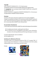
of documentations: „ For detailed product information, carefully read the User's Manual. „ For instructions on how to use GIGABYTE's unique features, read or download the information on/from the Support\Motherboard\Technology Guide page on our website. For product-related information, check on our - Gigabyte GA-G33M-S2L | Manual - Page 4
Box Contents ...6 OptionalItems...6 GA-G33M-S2L Motherboard Layout 7 Block Diagram...8 Chapter 1 Hardware Installation 9 1-1 Installation Precautions 9 1-2 Product Specifications 10 1-3 Installing the CPU and CPU Cooler 13 1-3-1 Installing the CPU 13 1-3-2 Installing the CPU Cooler 15 - Gigabyte GA-G33M-S2L | Manual - Page 5
Driver CD Information 52 3-4 Hardware Information 53 3-5 Contact Us ...53 Chapter 4 Unique Features 55 4-1 Xpress Recovery2 55 4-2 BIOS Update Utilities 60 4-2-1 Updating the BIOS with the Q-Flash Utility 60 4-2-2 Updating the BIOS with the @BIOS Utility 63 4-3 EasyTune 5 Pro 65 4-4 Windows - Gigabyte GA-G33M-S2L | Manual - Page 6
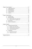
Box Contents GA-G33M-S2L motherboard Motherboard driver disk User's Manual Intel® LGA775 CPU Installation Guide One IDE cable and one floppy disk drive cable Two SATA 3Gb/s cables I/O Shield • The box contents above are for reference only and the actual - Gigabyte GA-G33M-S2L | Manual - Page 7
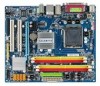
GA-G33M-S2L Motherboard Layout COMA KB_MS ATX_12V LGA775 DDRII1 DDRII2 CPU_FAN LPT VGA USB R_USB IDE ATX CI CLR_CMOS GA-G33M-S2L DDRII3 DDRII4 LAN AUDIO F_AUDIO RTL8111B PCIE_1 PCIE_16 IT8718 PCI1 PCI2 CODEC CD_IN SPDIF_O FDD Intel® G33 BAT MBIOS Intel® ICH9 SATAII0 SATAII1 - Gigabyte GA-G33M-S2L | Manual - Page 8
CLK (100 MHz) x1 RJ45 RTL8111B PCI Express Bus PCI Bus LGA775 Processor Host Interface Intel® G33 CPU CLK+/(333/266/200 MHz) DDR2 800/667 MHz Dual Channel Memory GMCH CLK (333/266/200 MHz) Intel® ICH9 CODEC BIOS ATA-100/66/33 IDE Channel 4 SATA 3Gb/s 12 USB Ports IT8718 Floppy LPT Port - Gigabyte GA-G33M-S2L | Manual - Page 9
manual and follow these procedures: • Prior to installation, do not remove or break motherboard S/N (ESD) wrist strap when handling electronic components such as a motherboard, CPU or memory. If you do not have an ESD wrist steps or have a problem related to the use of the product, please consult - Gigabyte GA-G33M-S2L | Manual - Page 10
/Intel® Pentium® 4 processor/ Intel® Celeron® processor in the LGA 775 package (Go to GIGABYTE's website for the latest CPU support list.) Š L2 cache varies with CPU Š 1333/1066/800 MHz FSB Š North Bridge: Intel® G33 Express Chipset Š South Bridge: Intel® ICH9 Š 4 x 1.8V DDR2 DIMM sockets supporting - Gigabyte GA-G33M-S2L | Manual - Page 11
port Š 3 x audio jacks (Line In/Line Out/Microphone) I/O Controller Š iTE IT8718 chip Hardware Monitor Š System voltage detection Š CPU temperature detection Š CPU/System fan speed detection Š CPU overheating warning Š CPU/System fan fail warning Š CPU fan speed control BIOS Š 1 x 8 Mbit - Gigabyte GA-G33M-S2L | Manual - Page 12
ICH9, hot plug is supported in Windows Vista only) and configure the SATA connectors for AHCI mode. (Refer to Chapter 2, "BIOS Setup," "Integrated Peripherals," for details on enabling AHCI.) (Note 3) Available functions in Easytune may differ by motherboard model. GA-G33M-S2L Motherboard - 12 - - Gigabyte GA-G33M-S2L | Manual - Page 13
so according to your hardware specifications including the CPU, graphics card, memory, hard drive, etc. 1-3-1 Installing the CPU A. Locate the alignment keys on the motherboard CPU socket and the notches on the CPU. LGA775 CPU Socket Alignment Key LGA 775 CPU Alignment Key Pin One Corner of the - Gigabyte GA-G33M-S2L | Manual - Page 14
pin one corner of the CPU socket (or you may align the CPU notches with the socket alignment keys) and gently insert the CPU into position. Step 5: Once the CPU is properly inserted, replace the load plate and push the CPU socket lever back into its locked position. GA-G33M-S2L Motherboard - 14 - - Gigabyte GA-G33M-S2L | Manual - Page 15
. Check that the Male and Female push pins are joined closely. (Refer to your CPU cooler installation manual for instructions on installing the cooler.) Step 5: After the installation, check the back of the motherboard. If the push pin is inserted as the picture above, the installation is complete - Gigabyte GA-G33M-S2L | Manual - Page 16
installed, a message which says memory is operating in Flex Memory Mode will appear during the POST. Intel® Flex Memory Technology offers greater flexibility to upgrade by allowing different memory sizes to be populated and remain in Dual Channel mode/performance. GA-G33M-S2L Motherboard - 16 - - Gigabyte GA-G33M-S2L | Manual - Page 17
power outlet to prevent damage to the memory module. DDR2 DIMMs are not compatible to DDR DIMMs. Be sure to install DDR2 DIMMs on this motherboard. Notch DDR2 DIMM A DDR2 memory module has a notch, so it can only fit in one direction. Follow the steps below to correctly install your memory - Gigabyte GA-G33M-S2L | Manual - Page 18
expansion card: • Make sure the motherboard supports the expansion card. Carefully read the manual that came with your expansion card. necessary, go to BIOS Setup to make any required BIOS changes for your expansion card(s). 7. Install the driver provided with the GA-G33M-S2L Motherboard - 18 - - Gigabyte GA-G33M-S2L | Manual - Page 19
LAN Port Off 10 Mpbs data rate instructions on setting up a 2/4/5.1-channel audio configuration in Chapter 5, "Configuring 2/4/5.1-Channel Audio." • When removing the cable connected to a back panel connector, first remove the cable from your device and then remove it from the motherboard - Gigabyte GA-G33M-S2L | Manual - Page 20
6 2 11 15 9 7 12 13 5 4 16 14 8 10 1) ATX_12V 2) ATX 3) CPU_FAN 4) SYS_FAN 5) FDD 6) IDE 7) SATAII0 / 1 / 4 / 5 8) PWR_LED 9) BAT 10) F_PANEL 11) F_AUDIO 12) CD_IN 13) SPDIF_O 14) F_USB1 / cable has been securely attached to the connector on the motherboard. GA-G33M-S2L Motherboard - 20 - - Gigabyte GA-G33M-S2L | Manual - Page 21
to all the components on the motherboard. Before connecting the power connector, first power connector mainly supplies power to the CPU. If the 12V power connector is 24 1 13 ATX ATX : Pin No. 1 2 3 4 5 6 7 8 9 10 11 12 Definition Pin No. 3.3V 13 3.3V 14 GND 15 +5V 16 GND 17 + - Gigabyte GA-G33M-S2L | Manual - Page 22
drives supported are: 360 KB, 720 KB, 1.2 MB, 1.44 MB, and 2.88 MB. Before connecting a floppy disk drive, be sure to locate pin 1 of the connector and the floppy disk drive cable. The pin 1 of the cable is typically designated by a stripe of different color. 33 1 34 2 GA-G33M-S2L Motherboard - Gigabyte GA-G33M-S2L | Manual - Page 23
configuring master/slave settings for the IDE devices, read the instructions from the device manufacturers.) 40 39 2 1 7) SATAII0/1/4/5 3Gb/s standard and are compatible with SATA 1.5Gb/s standard. Each SATA connector supports a single SATA device. Pin No. Definition 7 1 SATAII0 1 GND 7 - Gigabyte GA-G33M-S2L | Manual - Page 24
S3/S4/S5 Off 9) BAT(BATTERY) The battery provides power to keep the values (such as BIOS configurations, date, and time information) in the CMOS when the computer is turned off. Replace the must be handled in accordance with local environmental regulations. GA-G33M-S2L Motherboard - 24 - - Gigabyte GA-G33M-S2L | Manual - Page 25
10) F_PANEL (Front Panel Header) Connect the power switch, reset switch will be heard if no problem is detected at system startup. If a problem is detected, the BIOS may issue beeps in different patterns to indicate the problem. Refer to Chapter 5, "Troubleshooting," for information about beep codes - Gigabyte GA-G33M-S2L | Manual - Page 26
front panel audio module that has different wire assignments, please contact the chassis manufacturer. 12) CD_IN (CD In Connector) You may connect the audio cable that came with your optical drive to the header. 1 Pin No. Definition 1 CD-L 2 GND 3 GND 4 CD-R GA-G33M-S2L Motherboard - 26 - Gigabyte GA-G33M-S2L | Manual - Page 27
digital S/PDIF out. Via an optional S/PDIF out cable, this header can connect to an audio device that supports digital audio in. For purchasing the optional S/PDIF out cable, please contact the local dealer. Pin No. Definition 1 1 Power 2 SPDIFO 3 GND Pin 1 (the red wire) of the S/ - Gigabyte GA-G33M-S2L | Manual - Page 28
," for BIOS configurations). 16) CI (Chassis Intrusion Header) This motherboard provides a chassis detection feature that detects if the chassis cover has been removed. This function requires a chassis with chassis intrusion detection design. Pin No. Definition 1 Signal 1 2 GND GA-G33M-S2L - Gigabyte GA-G33M-S2L | Manual - Page 29
Windows-based utility that searches and downloads the latest version of BIOS from the Internet and updates the BIOS. For instructions on using the Q-Flash and @BIOS utilities, refer to Chapter 4, "BIOS Update Utilities." • Because BIOS flashing is potentially risky, if you do not encounter problems - Gigabyte GA-G33M-S2L | Manual - Page 30
The following screen may appear when the computer boots. Motherboard Model BIOS Version Award Modular BIOS v6.00PG, An Energy Star Ally Copyright (C) 1984-2007, Award Software, Inc. Intel G33 BIOS for G33M-S2L E11a . . . . : BIOS Setup/Q-Flash : XpressRecovery2 : Boot Menu - Gigabyte GA-G33M-S2L | Manual - Page 31
Exit Setup Exit Without Saving ESC: Quit F8: Q-Flash KLJI: Select Item F10: Save & Exit Setup F11: Save CMOS to BIOS F12: Load CMOS from BIOS Time, Date, Hard Disk Type... BIOS Setup Program Function Keys Move the selection bar to select an item Execute command or enter the submenu - Gigabyte GA-G33M-S2L | Manual - Page 32
CMOS and exit BIOS Setup. (Pressing can also carry out this task.) „ Exit Without Saving Abandon all changes and the previous settings remain in effect. Pressing to the confirmation message will exit BIOS Setup. (Pressing can also carry out this task.) GA-G33M-S2L Motherboard - 32 - Gigabyte GA-G33M-S2L | Manual - Page 33
[None] [None] [None] Drive A Floppy 3 Mode Support [1.44M, 3.5"] [Disabled] Halt On [All, But Keyboard of the three methods below: • Auto Lets BIOS automatically detect IDE/SATA devices during the POST. for faster system startup. • Manual Allows you to manually enter the specifications of the - Gigabyte GA-G33M-S2L | Manual - Page 34
manually 3 Mode Support Allows you BIOS POST. Base Memory Also called conventional memory. Typically, 640 KB will be reserved for the MS-DOS operating system. Extended Memory The amount of extended memory. Total Memory The total amount of memory installed on the system. GA-G33M-S2L Motherboard - Gigabyte GA-G33M-S2L | Manual - Page 35
system; set this item to Enabled for legacy operating system such as Windows NT4.0. (Default: Disabled) (Note) This item is present only if you install a CPU that supports this feature. For more information about Intel CPUs' unique features, please visit Intel's website. - 35 - BIOS Setup - Gigabyte GA-G33M-S2L | Manual - Page 36
only this memory for display. Options are: 8MB+1~2MB for GTT (default), 1MB+1~2MB for GTT. (Note) This item is present only if you install a CPU that supports this feature. For more information about Intel CPUs' unique features, please visit Intel's website. GA-G33M-S2L Motherboard - 36 - - Gigabyte GA-G33M-S2L | Manual - Page 37
driver to enable advanced Serial ATA features such as Native Command Queuing and hot plug. For more information about AHCI, please visit Intel Keyboard Support Allows USB keyboard to be used in MS-DOS. (Default: Disabled) (Note) Supported on Windows® Vista® operating system only. - 37 - BIOS - Gigabyte GA-G33M-S2L | Manual - Page 38
the figure above. When LAN Cable Is Functioning Normally... If no cable problem is detected on the LAN cable connected to a Gigabit hub or a 10/100 Mbps hub, the following message will appear: Start detecting at Port..... Link Detected --> 100Mbps Cable Length= 30m GA-G33M-S2L Motherboard - 38 - - Gigabyte GA-G33M-S2L | Manual - Page 39
mode; it will operate at a normal speed of 10/100/1000 Mbps in Windows mode or when the LAN Boot ROM is activated. When a Cable Problem Occurs... If a cable problem occurs on a specified pair of wires, the EPP (Enhanced Parallel Port), ECP (Extended Capabilities Port), ECP+EPP. - 39 - BIOS Setup - Gigabyte GA-G33M-S2L | Manual - Page 40
time. S3(STR) Enables the system to enter the ACPI S3 (Suspend to RAM) sleep state (default). In S3 sleep state, the system appears to be off a modem that supports wake-up function. (Default: Enabled) (Note) Supported on Windows® Vista® operating system only. GA-G33M-S2L Motherboard - 40 - - Gigabyte GA-G33M-S2L | Manual - Page 41
AC power, or the settings may not be effective. HPET Support (Note) Enables or disables High Precision Event Timer (HPET) for Windows® Vista® operating system. (Default: Enabled) HPET Mode ( the return of the AC power. (Note) Supported on Windows® Vista® operating system only. - 41 - BIOS Setup - Gigabyte GA-G33M-S2L | Manual - Page 42
Help F7: Optimized Defaults BIOS auto-assigns IRQ to the first PCI slot. (Default) Assigns IRQ 3,4,5,7,9,10,11,12,14,15 to the first PCI slot. BIOS auto-assigns IRQ to the second PCI slot. (Default) Assigns IRQ 3,4,5,7,9,10,11,12,14,15 to the second PCI slot. GA-G33M-S2L Motherboard - 42 - - Gigabyte GA-G33M-S2L | Manual - Page 43
device attached to the motherboard CI header. If the CPU Temperature Displays current CPU temperature. Current CPU/SYSTEM FAN Speed (RPM) Displays current CPU/system fan speed. CPU Warning Temperature Sets the warning threshold for CPU temperature. When CPU temperature exceeds the threshold, BIOS - Gigabyte GA-G33M-S2L | Manual - Page 44
board to default values.) • When the System Voltage Optimized item blinks in red, it is recommended that you set the System Voltage Control item to Auto to optimize the system voltage settings. (Note) This item appears only if you install a CPU that supports this feature. GA-G33M-S2L Motherboard - Gigabyte GA-G33M-S2L | Manual - Page 45
your system fails to boot after overclocking, please wait for 20 seconds to allow for automated system reboot, or clear the CMOS values to reset the board to default values. (Default: Disabled) CPU Host Frequency (Mhz) Allows you to manually set the CPU host frequency. This item is configurable - Gigabyte GA-G33M-S2L | Manual - Page 46
allows all DRAM timing control items below to be configurable. Options are: Auto (default), Manual. CAS Latency Time Options are: Auto (default), 3~6. DRAM RAS# to CAS# Delay Options are: Auto (default), 1~31. tRD Phase Adjustment Options are: Auto (default), 1~31. GA-G33M-S2L Motherboard - 46 - - Gigabyte GA-G33M-S2L | Manual - Page 47
System Voltage Control Determines whether to manually set the system voltages. Auto lets BIOS automatically set the system voltages as required. Manual allows all voltage control items below to be configurable. (Default: Manual) DDR2 OverVoltage Control Allows you to to set memory voltage. Normal - Gigabyte GA-G33M-S2L | Manual - Page 48
Press on this item and then press the key to load the optimal BIOS default settings. The BIOS defaults settings helps the system to operate in optimum state. Always load the Optimized defaults after updating the BIOS or after clearing the CMOS values. GA-G33M-S2L Motherboard - 48 - - Gigabyte GA-G33M-S2L | Manual - Page 49
Password Save & Exit Setup Exit Without Saving ESC: Quit F8: Q-Flash KLJI: Select Item F10: Save & Exit Setup F11: Save CMOS to BIOS F12: Load CMOS from BIOS Change/Set/Disable Password Press on this item and type the password with up to 8 characters and then press . You will be - Gigabyte GA-G33M-S2L | Manual - Page 50
Setup F11: Save CMOS to BIOS F12: Load CMOS from BIOS Abandon all Data Press on this item and press the key. This exits the BIOS Setup without saving the changes made in BIOS Setup to the CMOS. Press or to return to the BIOS Setup Main Menu. GA-G33M-S2L Motherboard - 50 - - Gigabyte GA-G33M-S2L | Manual - Page 51
other drivers. • After the drivers are installed, follow the onscreen instructions to restart your system. You can install other applications included in the motherboard driver disk. • For USB 2.0 driver support under the Windows XP operating system, please install the Windows XP Service Pack - Gigabyte GA-G33M-S2L | Manual - Page 52
all the tools and applications that GIGABYTE develops and some free software. You may press the Install button following an item to install it. 3-3 Driver CD Information This page provides information about the drivers, applications and tools in this driver disk. GA-G33M-S2L Motherboard - 52 - - Gigabyte GA-G33M-S2L | Manual - Page 53
3-4 Hardware Information This page provides information about the hardware devices on this motherboard. 3-5 Contact Us Check the contacts information of the GIGABYTE headquarter in Taiwan and the overseas branch offices on the last page of this manual. - 53 - Drivers Installation - Gigabyte GA-G33M-S2L | Manual - Page 54
GA-G33M-S2L Motherboard - 54 - - Gigabyte GA-G33M-S2L | Manual - Page 55
and drivers are installed. Windows® XP with SP1 or later • Xpress Recovery and Xpress Recovery2 are different utilities. For example, a backup file created with Xpress Recovery cannot be restored using Xpress Recovery2. • USB hard drives are not supported. • Hard drives in RAID/AHCI mode are not supported - Gigabyte GA-G33M-S2L | Manual - Page 56
for Xpress Recovery2 (10 GB or more is recommended; actual size requirements vary, depending on the amount of data) (Figure 2). Figure 1 Figure 2 3. Select a file system (for example, NTFS) and begin the installation of the operating system (Figure 3). Figure 3 GA-G33M-S2L Motherboard - 56 - - Gigabyte GA-G33M-S2L | Manual - Page 57
4. After the operating system is installed, right-click the My Computer icon on your desktop and select Manage (Figure 4). Go to Computer Management to check disk allocation. Xpress Recovery2 will save the backup file to the unallocated space (black stripe along the top)(Figure 5). Please note that - Gigabyte GA-G33M-S2L | Manual - Page 58
Inc. Intel G33 BIOS for G33M-S2L E11a . . . . : BIOS Setup/Q-Flash : XpressRecovery2 : Boot Menu : Qflash 09/21/2007-G33-ICH9-6A89OG06C-00 Figure 9 C. Using the Backup Function in Xpress Recovery2 1. Select BACKUP to start backing up your hard drive data (Figure 10). 2. Xpress - Gigabyte GA-G33M-S2L | Manual - Page 59
D. Using the Restore Function in Xpress Recovery2 Select RESTORE to restore the backup to your hard drive in case the system breaks down. The RESTORE option will not be present if no backup is created before (Figure 13, 14). Figure 13 Figure 14 E. Removing the Backup 1. If you wish to remove the - Gigabyte GA-G33M-S2L | Manual - Page 60
BIOS update file is saved to a hard drive in RAID/AHCI mode or a hard drive attached to an independent IDE/SATA controller, use the key during the POST to access Q-Flash. Award Modular BIOS v6.00PG, An Energy Star Ally Copyright (C) 1984-2007, Award Software, Inc. Intel G33 BIOS for G33M-S2L - Gigabyte GA-G33M-S2L | Manual - Page 61
key to select Update BIOS from Drive and press . • The Save Main BIOS to Drive option allows you to save the current BIOS file. • Q-Flash only supports USB flash drive or hard drives using FAT32/16/12 file system. • If the BIOS update file is saved to a hard drive in RAID/AHCI mode or a hard - Gigabyte GA-G33M-S2L | Manual - Page 62
Setup F11: Save CMOS to BIOS F12: Load CMOS from BIOS Load Optimized Defaults Press to load BIOS defaults Step 6: Select Save & Exit Setup and then press to save settings to CMOS and exit BIOS Setup. The procedure is complete after the system restarts. GA-G33M-S2L Motherboard - 62 - - Gigabyte GA-G33M-S2L | Manual - Page 63
and Using @BIOS: Use the motherboard driver disk included with the motherboard to install @BIOS. • Installing the @BIOS utility. • Accessing the @BIOS utility. Select @BIOS and click Install. Click Start>All Programs>GIGABYTE>@BIOS C. Options and Instructions: 1. Save the Current BIOS File In - Gigabyte GA-G33M-S2L | Manual - Page 64
in an unbootable system. • If the BIOS update file for your motherboard is not present on the @BIOS server site, please manually download the BIOS update file from GIGABYTE's website and follow the instructions in "Update the BIOS without Using the Internet Update Function" below. Step 4: As the - Gigabyte GA-G33M-S2L | Manual - Page 65
BIOS Setup program. EasyTune 5 Pro provides the following functions (Note 1): overclocking/overvoltage, C.I.A./M.I.B. (Note 2), smart fan control, and hardware monitoring and warning. (For instructions on using EasyTune5 Pro, read or download the information on/from the Support\Motherboard\Utility - Gigabyte GA-G33M-S2L | Manual - Page 66
ReadyBoost allows you to use flash memory on a Windows Vista certified USB flash drive to boost your computer's performance. You may enable ReadyBoost of memory to use for ReadyBoost acceleration is one to three times the amount of RAM installed in your computer. GA-G33M-S2L Motherboard - 66 - - Gigabyte GA-G33M-S2L | Manual - Page 67
. Before installing the audio driver, make sure the "Microsoft UAA Bus driver for High Definition Audio" has been installed from the motherboard driver disk and your operating system has been updated with the latest Service Pack for Windows. (Note) 2/4/5.1-Channel Audio Configurations: Refer to - Gigabyte GA-G33M-S2L | Manual - Page 68
4: Everytime you connect an audio device to an audio jack, the Connected device box appears. Select the device according to the type of device you connect. Then click OK to complete the configuration. Front Speaker Out Rear Speaker Out Center/Subwoofer Speaker Out GA-G33M-S2L Motherboard - 68 - - Gigabyte GA-G33M-S2L | Manual - Page 69
box, select the Disable front panel jack detection check box. Click OK to activiate the AC'97 functionality. When using an AC'97 front panel audio module, you can only have audio signals present on either the front or the back panel audio connections, but not both at the same time. - 69 - Appendix - Gigabyte GA-G33M-S2L | Manual - Page 70
on your motherboard. Pin 1 (the red wire) of the S/PDIF out cable must align with pin 1 of the SPDIF_O header. Incorrect connection may render the device unusable or even result in damage to the device. Step 2: Secure the metal bracket to the chassis back panel with a screw. GA-G33M-S2L Motherboard - Gigabyte GA-G33M-S2L | Manual - Page 71
Cable Step 3: Connect a S/PDIF coaxial cable or a S/PDIF optical cable (either one) to an external decoder for transmitting the S/PDIF digital audio signals. S/PDIF Optical Cable B. Configuring S/PDIF out: Click the tool icon in the DIGITAL section. In the S/PDIF Settings dialog box, select - Gigabyte GA-G33M-S2L | Manual - Page 72
Configuring Microphone Recording Step 1: After installing the audio driver, the Audio Manager icon will appear in your system tray. Double-click the icon to access the Audio Control Panel. Step 2: Connect your microphone to click it to open the volume control panel GA-G33M-S2L Motherboard - 72 - - Gigabyte GA-G33M-S2L | Manual - Page 73
and click OK to complete. Step 5: Next, while in Master Volume, go to Options and click Properties. In the Mixer device list, select Realtek HD Audio Input. Then set the recording sound level properly. Do NOT mute the recording sound, or you will not hear any sound when playing back the - Gigabyte GA-G33M-S2L | Manual - Page 74
begin the sound recording. 5-1-4 Using the Sound Recorder Recording the Sound: 1. Make sure you have connected the audio input device (e.g. microphone) to the computer. 2. On the File menu, choose New. 3. To record of a file or the Fast Backward button to the end. GA-G33M-S2L Motherboard - 74 - - Gigabyte GA-G33M-S2L | Manual - Page 75
5-2 Troubleshooting 5-2-1 Frequently Asked Questions To read more FAQs for your motherboard, please go to the Support\Motherboard\FAQ page on GIGABYTE's website. Q: In the BIOS Setup program, why are some BIOS options missing? A: Some advanced options are hidden in the BIOS Setup program. Press < - Gigabyte GA-G33M-S2L | Manual - Page 76
insert the memory into the memory socket. The problem is verified and solved. Press to enter BIOS Setup. Select "Load Fail-Safe Defaults" (or "Load Optimized Defaults"). Select "Save & Exit Setup" to save changes and exit BIOS Setup. A (Continued...) GA-G33M-S2L Motherboard - 76 - - Gigabyte GA-G33M-S2L | Manual - Page 77
is verified and solved. END If the procedure above is unable to solve your problem, contact the place of purchase or local dealer for help. Or go to the Support\Technical Service Zone page to submit your question. Our customer service staff will reply you as soon as possible. - 77 - Appendix - Gigabyte GA-G33M-S2L | Manual - Page 78
product. Restriction of Hazardous Substances (RoHS) Directive Statement GIGABYTE products have not intended to add and safe from hazardous office, your household waste disposal service or where you purchased the manual and we will be glad to help you with your effort. GA-G33M-S2L Motherboard - 78 - - Gigabyte GA-G33M-S2L | Manual - Page 79
Finally, we suggest that you practice other environmentally friendly actions by understanding and using the energy-saving features of this product (where applicable), recycling the inner and outer packaging (including shipping containers) this product was delivered in, and by disposing of or - Gigabyte GA-G33M-S2L | Manual - Page 80
GA-G33M-S2L Motherboard - 80 - - Gigabyte GA-G33M-S2L | Manual - Page 81
- 81 - Appendix - Gigabyte GA-G33M-S2L | Manual - Page 82
GA-G33M-S2L Motherboard - 82 - - Gigabyte GA-G33M-S2L | Manual - Page 83
Taipei 231, Taiwan TEL: +886-2-8912-4888 FAX: +886-2-8912-4003 Tech. and Non-Tech. Support (Sales/Marketing) : http://ggts.gigabyte.com.tw WEB address (English): http://www.gigabyte.com.tw WEB address (Chinese): http://www.gigabyte.tw U.S.A. G.B.T. INC. TEL: +1-626-854-9338 FAX: +1-626-854-9339 Tech - Gigabyte GA-G33M-S2L | Manual - Page 84
your language in the language list on the top right corner of the website. GIGABYTE Global Service System To submit a technical or non-technical (Sales/ Marketing) question, please link to : http://ggts.gigabyte.com.tw Then select your language to enter the system. GA-G33M-S2L Motherboard - 84 -
-
 1
1 -
 2
2 -
 3
3 -
 4
4 -
 5
5 -
 6
6 -
 7
7 -
8
-
9
-
10
-
11
-
12
-
13
-
14
-
15
-
16
-
17
-
18
-
19
-
20
-
21
-
22
-
23
-
24
-
25
-
26
-
27
-
28
-
29
-
30
-
31
-
32
-
33
-
34
-
35
-
36
-
37
-
38
-
39
-
40
-
41
-
42
-
43
-
44
-
45
-
46
-
47
-
48
-
49
-
50
-
51
-
52
-
53
-
54
-
55
-
56
-
57
-
58
-
59
-
60
-
61
-
62
-
63
-
64
-
65
-
66
-
67
-
68
-
69
-
70
-
71
-
72
-
73
-
74
-
75
-
76
-
77
-
78
-
79
-
80
-
81
-
82
-
83
-
84
 |
 |

GA-G33M-S2L
LGA775 socket motherboard for Intel
®
Core
TM
processor family/
Intel
®
Pentium
®
processor family/Intel
®
Celeron
®
processor family
User's Manual
Rev. 1001
12ME-G33MS2L-1001R