Gigabyte GA-IMB410M User Manual - Page 19
SPKR Speaker Header, VOL_CTRL Speaker Control Header, F_USB1/F_USB2 USB 2.0/1.1 Headers, Pin No.
 |
View all Gigabyte GA-IMB410M manuals
Add to My Manuals
Save this manual to your list of manuals |
Page 19 highlights
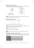
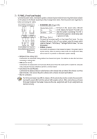
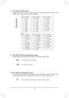
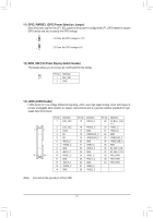
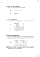
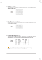
17) SPKR (Speaker Header) This speaker header is connected to a L/R audio pins from the board to support the 3W (4ohm) stereo speaker on your AIO chassis. 1 4 Pin No. 1 2 3 4 Definition Speaker OUT RSpeaker OUT R+ Speaker OUT LSpeaker OUT L+ 18) VOL_CTRL (Speaker Control Header) The header connects to the volume control button of the monitor to control the volume. This feature requires a software update to be enabled. Pin No. Definition 1 VOL_DW 1 2 GND 3 VOL_UP 19) F_USB1/F_USB2 (USB 2.0/1.1 Headers) The headers conform to USB 2.0/1.1 specification. Each USB header can provide two USB ports via an optional USB bracket. For purchasing the optional USB bracket, please contact the local dealer. 9 1 10 2 Pin No. 1 2 3 4 5 Definition Power (5V) Power (5V) USB DXUSB DYUSB DX+ Pin No. 6 7 8 9 10 Definition USB DY+ GND GND No Pin NC •• Do not plug the IEEE 1394 bracket (2x5-pin) cable into the USB 2.0/1.1 header. •• Prior to installing the USB bracket, be sure to turn off your computer and unplug the power cord from the power outlet to prevent damage to the USB bracket. - 19 -
-
 1
1 -
2
-
3
-
4
-
5
-
6
-
7
-
8
-
9
-
10
-
11
-
12
-
13
-
 14
14 -
 15
15 -
 16
16 -
 17
17 -
 18
18 -
 19
19 -
 20
20 -
 21
21 -
 22
22 -
 23
23 -
 24
24 -
25
-
26
-
27
-
28
-
29
-
30
-
31
-
32
-
33
-
34
-
35
-
36
-
37
 |
 |
