Gigabyte GA-K8NXP-SLI User Manual
Gigabyte GA-K8NXP-SLI Manual
 |
View all Gigabyte GA-K8NXP-SLI manuals
Add to My Manuals
Save this manual to your list of manuals |
Gigabyte GA-K8NXP-SLI manual content summary:
- Gigabyte GA-K8NXP-SLI | User Manual - Page 1
GA-K8NXP-SLI AMD Socket 939 Processor Motherboard User's Manual Rev. 1004 12ME-K8NXPSLI-1004 - Gigabyte GA-K8NXP-SLI | User Manual - Page 2
Motherboard GA-K8NXP-SLI Dec. 14, 2004 Motherboard GA-K8NXP-SLI Dec. 14, 2004 - Gigabyte GA-K8NXP-SLI | User Manual - Page 3
. „ For detailed product information and specifications, please carefully read the "Product User Manual". „ For detailed information related to Gigabyte's unique features, please go to the "Technology Guide" section on Gigabyte's website to read or download the information you need. For more product - Gigabyte GA-K8NXP-SLI | User Manual - Page 4
Table of Contents GA-K8NXP-SLI Motherboard Layout 6 Block Diagram ...7 Chapter 1 Hardware Installation 9 1-1 Considerations Prior to Installation 9 1-2 Feature Summary 10 1-3 Installation of the CPU and Fan Heat Sink 12 1-3-1 Installation of the CPU 12 1-3-2 Installation of the Fan Heat Sink - Gigabyte GA-K8NXP-SLI | User Manual - Page 5
55 4-1 Unique Software Utilities 55 4-1-1 EasyTune 5 Introduction 55 4-1-2 Xpress Recovery Introduction 56 4-1-3 Flash BIOS Method Introduction 59 4-1-4 Serial ATA BIOS Setting Utility Introduction 70 4-1-5 2- / 4- / 6- / 8- Channel Audio Function Introduction 76 4-2 Troubleshooting 82 - 5 - - Gigabyte GA-K8NXP-SLI | User Manual - Page 6
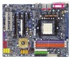
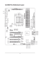
GA-K8NXP-SLI Motherboard Layout KB_MS VRM_CONN SPDIF_I ATX_12V ATX SPDIF_O Socket 939 COMA LPT USB LAN2 IDE2 USB LAN1 AUDIO1 AUDIO2 CPU_FAN VITESSE 8201 phy F_AUDIO Marvell 8053 PCIE_1 PCIE_2 Backup Main BIOS BIOS PCIE_16_1 SLI Switch Module Socket PCIE_16_2 nVIDIA® nForce4 SLI - Gigabyte GA-K8NXP-SLI | User Manual - Page 7
2 PCI Express x 1 Ports PCI-ECLK (100MHz) LAN 1 RJ45 Marvell 8053 LAN 2 RJ45 PCI Express x 1 Bus VITESSE 8201 phy PCI Bus AMD K8 Socket 939 CPU CPUCLK+/-(200MHz) DDR 400/333/266/200MHz DIMM Dual Channel Memory Hyper Transport Bus nVIDIA® nForce4 SLI BIOS 4 SATA 3Gb/s ATA33/66/100/133 IDE - Gigabyte GA-K8NXP-SLI | User Manual - Page 8
- 8 - - Gigabyte GA-K8NXP-SLI | User Manual - Page 9
instructions below: 1. Please turn off the computer and unplug its power cord. 2. When handling the motherboard , avoid touching any metal leads or connectors. 3. It is best to wear an electrostatic discharge (ESD) cuff when handling electronic components (CPU motherboard problem manual - Gigabyte GA-K8NXP-SLI | User Manual - Page 10
Summary CPU Chipset Memory Slots IDE Connections FDD Connections Onboard SATA Peripherals Onboard LAN Onboard Audio I/O Control Š Socket 939 for AMD AthlonTM 64 / 64 FX processor (K8) Š 2000MT/s system bus Š Supports core frequencies in excess of 3000+ and faster Š nVIDIA® nForce4 SLI Chipset - Gigabyte GA-K8NXP-SLI | User Manual - Page 11
Monitor Onboard SATA RAID Š Š BIOS Š Š Additional Features Š Š Overclocking Š Form Factor Š System voltage detection CPU temperature detection CPU / System / Power fan speed detection CPU warning temperature CPU fan failure warning CPU smart fan control Onboard nForce4 SLI chipset - Gigabyte GA-K8NXP-SLI | User Manual - Page 12
down on the middle of the CPU and gently press the metal lever back into its original position. Please use extra care when installing the CPU. The CPU will not fit if positioned incorrectly. Rather than applying force, please change the positioning of the CPU. GA-K8NXP-SLI Motherboard - 12 - - Gigabyte GA-K8NXP-SLI | User Manual - Page 13
sink paste on the surface of the CPU. Install all the fan heat sink components (Please refer to the fan heat sink manual for detailed installation instructions). Fig.2 Please connect the fan heat sink power connector to the CPU_FAN connector located on the motherboard so that the fan heat sink can - Gigabyte GA-K8NXP-SLI | User Manual - Page 14
fit in one direction. Insert the DIMM memory module vertically into the DIMM socket. Then push it down. Fig.2 Close the plastic clip at both edges of the DIMM sockets to lock the DIMM module. Reverse the installation steps when you wish to remove the DIMM module. GA-K8NXP-SLI Motherboard - 14 - - Gigabyte GA-K8NXP-SLI | User Manual - Page 15
English Dual Channel Memory Configuration The GA-K8NXP-SLI supports the Dual Channel Technology. After operating the Dual Channel Technology, the bandwidth of Memory Bus will double. Due to CPU limitation, if you want to operate the Dual Channel Technology, please follow the guidelines below for - Gigabyte GA-K8NXP-SLI | User Manual - Page 16
outlined below: 1. Read the related expansion card's instruction document before install the expansion card into the computer the computer, if necessary, setup BIOS utility of expansion card from BIOS. 8. Install related driver from the operating system. Installing a GA-K8NXP-SLI Motherboard - 16 - - Gigabyte GA-K8NXP-SLI | User Manual - Page 17
. The K8DPS can work in a Dual Power System: Parallel Mode-K8DPS and motherboard CPU power can work simultaneously, providing a total of 6-phase power circuit. How to install K8DPS? 1. The K8DPS socket (VRM_CONN) has a notch, so the K8DPS can only fit in one direction. 2. Insert the K8DPS vertically - Gigabyte GA-K8NXP-SLI | User Manual - Page 18
requirements will depend on your overall system configurations. You need a power supply that can provide sufficient and stable power to your system and the two SLI graphics cards. Please refer to the table below to check recommended power for different systems. GA-K8NXP-SLI Motherboard - 18 - - Gigabyte GA-K8NXP-SLI | User Manual - Page 19
English III. Supported Operating Systems: Only Windows XP operating system is currrently supported by the NVIDIA SLI technology. Enabling SLI Mode-Follow the steps below to enable SLI Mode. Note that as the switch module is inserted in the socket in the Normal Mode direction by factory default, the - Gigabyte GA-K8NXP-SLI | User Manual - Page 20
in BIOS Setup Driver Setting: Step 1: After installing graphics card driver SLI multi-GPU from the side menu and then select the Enable SLI multi-GPU checkbox in the SLI multi-GPU dialog box. System will restart after you click Apply. Then the SLI configuration is completed. GA-K8NXP-SLI Motherboard - Gigabyte GA-K8NXP-SLI | User Manual - Page 21
The SPDIF output is capable of providing digital audio to external speakers or compressed AC3 data to speeds of 10/100/ 1000Mbps. LAN Port 1 The provided Internet connection supports USB controller. If your OS does not support USB controller, please contact OS vendor for possible patch or driver - Gigabyte GA-K8NXP-SLI | User Manual - Page 22
software to configure 2-/4-/6-/8-channel audio functioning. 1-9 Connectors Introduction 13 8 11 13 1) ATX_12V 2) ATX (Power Connector) 3) CPU_FAN 4) SYS_FAN 5) PWR_FAN 6) NB_FAN 7) FDD 8) IDE1 / IDE2 9) S_ATA0/1/2/3_SB 10) SATA0/1/2/3_SII GA-K8NXP-SLI Motherboard 2 5 7 19 6 18 9 12 14 4 15 - Gigabyte GA-K8NXP-SLI | User Manual - Page 23
all components and devices are properly installed. Align the power connector with its proper location on the motherboard and connect tightly. The ATX_12V power connector mainly supplies power to the CPU. If the ATX_12V power connector is not connected, the system will not start. Caution! Please use - Gigabyte GA-K8NXP-SLI | User Manual - Page 24
to prevent system overheating and failure. Caution! Please remember to connect the power to the CPU fan to prevent CPU overheating and failure. 1 CPU_FAN Pin No. 1 2 3 Definition GND +12V Sense 1 black cable is GND) 1 Pin No. Definition 1 +12V 2 GND GA-K8NXP-SLI Motherboard - 24 - - Gigabyte GA-K8NXP-SLI | User Manual - Page 25
FDD cable while the other end of the cable connects to the FDD drive. The types of FDD drives supported are: 360KB, 720KB, 1.2MB, 1.44MB and 2.88MB. Please connect the red power connector wire to , please refer to the instructions located on the IDE device). 40 39 2 - 25 - 1 Hardware Installation - Gigabyte GA-K8NXP-SLI | User Manual - Page 26
refer to the BIOS setting for the SATA controller(s)and install the proper driver in order to work properly. 7 1 S_ATA_SB (Controlled by nForce4 SLI) 7 1 Pin No. 1 2 3 4 5 6 7 SATA_SII (Controlled by Sil3114) Definition GND TXP TXN GND RXN RXP GND 11) F_AUDIO (Front Audio Panel Connector) If - Gigabyte GA-K8NXP-SLI | User Manual - Page 27
English 12) F_PANEL (Front Panel Jumper) Please connect the power LED, PC speaker, reset switch and power switch etc of your chassis front panel to the F_PANEL connector according to the pin assignment below. Speaker Connector Power Switch Message LED/ Power/ Sleep LED SPEAK- 20 19 SPEAK+ PWPW+ - Gigabyte GA-K8NXP-SLI | User Manual - Page 28
English 13) CD_IN (CD In Connector) Connect CD-ROM or DVD-ROM audio out to the connector. Pin No. Definition 1 1 CD-L 2 GND 3 GND 4 CD-R 14) PWR_LED PWR_LED will blink when the system enters suspend mode. Pin No. Definition 1 MPD+ 2 MPD- 1 3 MPD- GA-K8NXP-SLI Motherboard - 28 - - Gigabyte GA-K8NXP-SLI | User Manual - Page 29
English 15) IR_CIR Make sure the pin 1 on the IR device is align with pin one the connector. To enable the IR/CIR function, you are required to purchase an optional IR/CIR module. To use IR function only, please connect IR module to Pin1 to Pin5. Be careful with the polarity of the IR/CIR connector - Gigabyte GA-K8NXP-SLI | User Manual - Page 30
header. To clear CMOS, temporarily short 1-2 pin. Default doesn't include the jumper to prevent from improper use of this header. Open: Normal 1 Short: Clear CMOS 1 GA-K8NXP-SLI Motherboard - 30 - - Gigabyte GA-K8NXP-SLI | User Manual - Page 31
is incorrectly replaced. Replace only with the same or equivalent type recommended by the manufacturer. Dispose of used batteries according to the manufacturer's instructions. If you want to erase CMOS... 1. Turn OFF the computer and unplug the power cord. 2. Take out the battery gently and put it - Gigabyte GA-K8NXP-SLI | User Manual - Page 32
English GA-K8NXP-SLI Motherboard - 32 - - Gigabyte GA-K8NXP-SLI | User Manual - Page 33
its original settings. If you wish to upgrade to a new BIOS, either Gigabyte's Q-Flash or @BIOS utility can be used. Q-Flash allows the user to quickly and easily update or backup BIOS without entering the operating system. @BIOS is a Windows-based utility that does not require users to boot to DOS - Gigabyte GA-K8NXP-SLI | User Manual - Page 34
to search the advanced option hidden.Please Load Optimized Defaults in the BIOS when somehow the system works not stable as usual. This action Intelligent Tweaker(M.I.T.) This setup page is to control CPU clock and frequency ratio. „ Load Optimized Defaults Optimized GA-K8NXP-SLI Motherboard - 34 - - Gigabyte GA-K8NXP-SLI | User Manual - Page 35
English „ Set User Password Change, set, or disable password. It allows you to limit access to the system. „ Save & Exit Setup Save CMOS value settings to CMOS and exit setup. „ Exit Without Saving Abandon all CMOS value changes and exit setup. - 35 - BIOS Setup - Gigabyte GA-K8NXP-SLI | User Manual - Page 36
year Sun. to Sat. Drive A Floppy 3 Mode Support [1.44M, 3.5"] [Disabled] Jan. to Dec. Halt from Sun to Sat, determined by the BIOS and is display only Month Day Year The Manual detection step and allow for faster system start up. User can manually GA-K8NXP-SLI Motherboard - 36 - - Gigabyte GA-K8NXP-SLI | User Manual - Page 37
3.5" 3.5 inch double-sided drive; 2.88M byte capacity. Floppy 3 Mode Support (for Japan Area) Disabled Normal Floppy Drive. (Default value) Drive A that may be detected and you will be prompted. All Errors Whenever the BIOS detects a non-fatal error the system will be stopped. All, But - Gigabyte GA-K8NXP-SLI | User Manual - Page 38
SCSI, RAID, BIOS can not tell from 720K, 1.2M or 1.44M drive type as they are all 80 tracks. Disabled BIOS will not search for the type of floppy disk drive by track number. Note that there will not be any warning message if the drive installed is 360K. (Default value) GA-K8NXP-SLI Motherboard - Gigabyte GA-K8NXP-SLI | User Manual - Page 39
you to select the first initiation of the monitor display from which card when you install a PCI card and a PCI Express VGA card on the motherboard. PCI slot Set Init Display First to PCI VGA card. PEG Set Init Display First to PCI Express VGA card (Slot1). (Default value) PEG (Slot2 - Gigabyte GA-K8NXP-SLI | User Manual - Page 40
Award Software Integrated Peripherals USB Keyboard Support USB Mouse Support AC97 Audio Onboard 1394 Onboard LAN control Onboard LAN Boot ROM SATA RAID-5 Function Onboard Serial Port 1 Default Value) Disabled Disable IDE DMA transfer access. GA-K8NXP-SLI Motherboard - 40 - F1: General Help - Gigabyte GA-K8NXP-SLI | User Manual - Page 41
nForce4 SLI chipset) Enabled Enable Serial-ATA 1 support. (Default Value) Disabled Disable Serial-ATA 1 support. SATA 1 Primary RAID Enabled Enable SATA 1 1st SATA RAID function.(Default value) Disabled Disable this function. SATA 1 Secondary RAID Enabled Enable SATA 1 2nd SATA RAID - Gigabyte GA-K8NXP-SLI | User Manual - Page 42
. Enable onboard Serial port 1 and address is 3E8/IRQ4. 2E8/IRQ3 Disabled Enable onboard Serial port 1 and address is 2E8/IRQ3. Disable onboard Serial port 1. GA-K8NXP-SLI Motherboard - 42 - - Gigabyte GA-K8NXP-SLI | User Manual - Page 43
320. Disabled Disable this function. (Default value) CIR Port IRQ 5 Set CIR Port IRQ to 5. 11 Set CIR Port IRQ to 11. (Default value) - 43 - BIOS Setup - Gigabyte GA-K8NXP-SLI | User Manual - Page 44
to POWER ON system. If Power-On by Alarm is Enabled. Day of Month Alarm : Everyday, 1~31 Time (hh: mm: ss) Alarm : (0~23) : (0~59) : (0~59) GA-K8NXP-SLI Motherboard - 44 - - Gigabyte GA-K8NXP-SLI | User Manual - Page 45
, the system will be in "Off" state. (Default value) Full-On When AC-power back to the system, the system always in "On" state. - 45 - BIOS Setup - Gigabyte GA-K8NXP-SLI | User Manual - Page 46
Assign Auto Auto assign IRQ to onboard device. (Default value) 3,4,5,7,9,10,11,12,14,15 Set IRQ 3,4,5,7,9,10,11,12,14,15 to onboard device. GA-K8NXP-SLI Motherboard - 46 - - Gigabyte GA-K8NXP-SLI | User Manual - Page 47
fail warning function. CPU Smart FAN Control Disabled Disable this function. Enabled When this function is enabled, CPU fan will run at different speed depending on CPU temperature. Users can adjust the fan speed with Easy Tune based on their requirements. (Default value) - 47 - BIOS Setup - Gigabyte GA-K8NXP-SLI | User Manual - Page 48
Normal CPU Vcore Display your CPU normal voltage. Core Power voltage control Normal Set core power voltage as required. (Default value) +0.1v Increase core power voltage +0.1V. +0.2v Increase core power voltage +0.2V. +0.3v Increase core power voltage +0.3V. GA-K8NXP-SLI Motherboard - 48 - Gigabyte GA-K8NXP-SLI | User Manual - Page 49
DDR voltage control Please note that by overclocking your system through the increase of the DDR voltage, damage to the memory may occur. Normal Supply DDR voltage as Save & Exit Setup Exit Without Saving ESC: Quit F8: Dual BIOS/Q-Flash KLJI: Select Item F10: Save & Exit Setup Change/Set/ - Gigabyte GA-K8NXP-SLI | User Manual - Page 50
select "Setup" at "Password Check" in Advance BIOS Features Menu, you will be prompted only when BIOS/Q-Flash KLJI: Select Item F10: Save & Exit Setup Abandon all Data Type "Y" will quit the Setup Utility without saving to RTC CMOS. Type "N" will return to Setup Utility. GA-K8NXP-SLI Motherboard - Gigabyte GA-K8NXP-SLI | User Manual - Page 51
will continue to install other drivers. System will reboot automatically after install the drivers, afterward you can install others application. For USB2.0 driver support under Windows XP operating system, please use Windows Service Pack. After install Windows Service Pack, it will show a question - Gigabyte GA-K8NXP-SLI | User Manual - Page 52
Software Application This page displays all the tools that Gigabyte developed and some free software, you can choose anyone you want and press "install" to install them. 3-3 Software Information This page lists the contents of software and drivers in this CD-title. GA-K8NXP-SLI Motherboard - 52 - - Gigabyte GA-K8NXP-SLI | User Manual - Page 53
English 3-4 Hardware Information This page lists all device you have for this motherboard. 3-5 Contact Us Please see the last page for details. - 53 - Drivers Installation - Gigabyte GA-K8NXP-SLI | User Manual - Page 54
English GA-K8NXP-SLI Motherboard - 54 - - Gigabyte GA-K8NXP-SLI | User Manual - Page 55
5 presents the most convenient Windows based system performance enhancement and manageability utility. Featuring several powerful yet easy to use tools such as 1) Overclocking for enhancing system performance, 2) C.I.A. and M.I.B. for special enhancement for CPU and Memory, 3) Smart-Fan control for - Gigabyte GA-K8NXP-SLI | User Manual - Page 56
power on. . . Verifying DMI Pool Data Boot from CD: Boot from CD: Xpress Recovery V1.0 (C) Copy Right 2003. GIGABYTE Technology CO. , Ltd. 1. Execute Backup Utility 2. Execute Restore Utility 3. Remove Backup Image 4. Set Password 5. Exit and Restart Build 2011 GA-K8NXP-SLI Motherboard - 56 - - Gigabyte GA-K8NXP-SLI | User Manual - Page 57
1984-2004, Award Software, Inc. Intel 865PE AGPSet BIOS for 8IPE1000MT F1 Check System Health OK . . F9 For Xpress Recovery Xpress Recovery V1.0 (C) Copy Right 2003. GIGABYTE Technology CO. , Ltd. 1. Execute Backup Utility 2. Execute driver and software installations are complete. - 57 - Appendix - Gigabyte GA-K8NXP-SLI | User Manual - Page 58
your system and back up data as a backup image in your hard drive. Not all systems support access to Xpress Recovery by pressing the F9 key during computer power on. If this is the case password requirement. 5. Exit and Restart: Exit and restart your computer. GA-K8NXP-SLI Motherboard - 58 - - Gigabyte GA-K8NXP-SLI | User Manual - Page 59
Enable Copy Main ROM Data to Backup Load Default Settings Save Settings to CMOS Q-Flash Utility Update Main BIOS from Floppy Update Backup BIOS from Floppy Save Main BIOS to Floppy Save Backup BIOS to Floppy PgDn/PgUp: Modify : Move ESC: Reset 512K 512K F10: Power Off - 59 - Appendix - Gigabyte GA-K8NXP-SLI | User Manual - Page 60
that the Backup BIOS works normally and could automatically recover the Main BIOS. (This auto recovery utility is set by system automatically and can't be changed by user.) Load Default Settings Load dual BIOS default value. Save Settings to CMOS Save revised setting. GA-K8NXP-SLI Motherboard - 60 - Gigabyte GA-K8NXP-SLI | User Manual - Page 61
Part One. If your motherboard has single-BIOS, please refer to Part Two. Part One: Updating BIOS with Q-FlashTM Utility on Dual BIOS Motherboards. Some of Gigabyte motherboards are equipped with dual BIOS. In the BIOS menu of the motherboards supporting Q-Flash and Dual BIOS, the Q-Flash utility and - Gigabyte GA-K8NXP-SLI | User Manual - Page 62
Enter key on your keyboard to enable execution of the task. Action bar: Contains the names of four actions needed to operate the Q-Flash/Dual BIOS utility. Pressing the buttons mentioned on your keyboards to perform these actions. GA-K8NXP-SLI Motherboard - 62 - - Gigabyte GA-K8NXP-SLI | User Manual - Page 63
English Using the Q-FlashTM utility: This section tells you how to update BIOS using the Q-Flash utility. As described in the "Before you begin" section above, you must prepare a floppy disk having the BIOS file for your motherboard and insert it to your computer. If you have already put the floppy - Gigabyte GA-K8NXP-SLI | User Manual - Page 64
Primary Master : FUJITSU MPE3170AT ED-03-08 Primary Slave : None Secondary Master : CREATIVEDVD-RM DVD1242E BC101 Secondary Slave : None Press DEL to enter SETUP / Dual BIOS / Q-Flash / F9 For Xpress Recovery 09/23/2003-i875P-6A79BG03C-00 GA-K8NXP-SLI Motherboard - 64 - - Gigabyte GA-K8NXP-SLI | User Manual - Page 65
Disk Type... Press Y on your keyboard to save and exit. Part Two: Updating BIOS with Q-FlashTM Utility on Single-BIOS Motherboards. This part guides users of single-BIOS motherboards how to update BIOS using the Q-FlashTM utility. CMOS Setup Utility-Copyright (C) 1984-2004 Award Software Standard - Gigabyte GA-K8NXP-SLI | User Manual - Page 66
SyCs:tRemeset F10:Power Off Do not trun off power or reset your system at this stage!! After BIOS file is read, you'll see a confirmation dialog box asking you "Are you sure to update BIOS?" Please do not take out the floppy disk when it begins flashing BIOS. GA-K8NXP-SLI Motherboard - 66 - - Gigabyte GA-K8NXP-SLI | User Manual - Page 67
file becomes F4 after updating Award Modular BIOS v6.00PG, An Energy Star Ally Copyright (C) 1984-2003, Award Software, Inc. Intel 845GE AGPSet BIOS for 8GE800 F4 Check System Health OK Main Processor : Intel Pentium(R) 4 1.7GHz (100x17.0) Memory Testing : 122880K OK - Gigabyte GA-K8NXP-SLI | User Manual - Page 68
Update" icon. b. Click "Update New BIOS". c. Please select "All Files" in dialog box while opening the old file. d. Please search for BIOS unzip file, downloading from internet or any other methods (such as: K8NS939.D2). e. Complete update process following the instruction. GA-K8NXP-SLI Motherboard - Gigabyte GA-K8NXP-SLI | User Manual - Page 69
II, be sure that motherboard's model name in BIOS unzip file are the same as your motherboard's. Otherwise, your system won't boot. III. In method I, if the BIOS file you need cannot be found in @BIOSTM server, please go onto Gigabyte's website for downloading and updating it according to method II - Gigabyte GA-K8NXP-SLI | User Manual - Page 70
4-1-4 Serial ATA BIOS Setting Utility Introduction RAID Levels RAID (Redundant Array of RAID levels which the nVIDIA® nForce4 SLI chipset supports are RAID 0, RAID 1, RAID 0+RAID 1 and JBOD. RAID 0 (Striping) RAID really a RAID and does not support fault tolerance. GA-K8NXP-SLI Motherboard - 70 - - Gigabyte GA-K8NXP-SLI | User Manual - Page 71
more detailed setup information, please visit "Support\ Motherboard\ Technology Guide section" on our website at http:\\www.gigabyte.com.tw to read or download the information you need.) Configuring the Nvidia RAID BIOS The NVRAID BIOS setup lets you choose the RAID array type and which hard drives - Gigabyte GA-K8NXP-SLI | User Manual - Page 72
NVIDIA RAID Utility Nov 5 2004 - Define a New Array - Striping Block: Optimal Free Disks Loc Disk Model Name Array Disks Loc Disk Model Name [ ] Add 2.0.M ST3120026AS 2.1.M ST3120026AS [ ] Del [ESC] Quit [F6] Back [F7] Finish [TAB] Navigate [ ] Select [ENTER] Popup GA-K8NXP-SLI Motherboard - Gigabyte GA-K8NXP-SLI | User Manual - Page 73
] Quit [F6] Back [F7] Finish [TAB] Navigate [ ] Select [ENTER] Popup Press Y if you want to wipe out all the data from the RAID array, otherwise press N. You must choose Yes if the drives were previously used as RAID drives. The Array List window appears, where you can review the RAID arrays that - Gigabyte GA-K8NXP-SLI | User Manual - Page 74
out all the data, otherwise press N. Press Enter again to go back to the previous screen and then press Ctrl + X to exit the RAID setup. Now that the RAID setup has been configured from the RAID BIOS, the next step is to configure and load drivers under Windows. GA-K8NXP-SLI Motherboard - 74 - - Gigabyte GA-K8NXP-SLI | User Manual - Page 75
recognized during the Windows setup process. First of all, copy the driver for the SATA controller from the motherboard driver CD-ROM to a floppy disk. See the instructions below about how to copy the driver in MS-DOS mode(Note1). Prepare a startup disk that has CD-ROM support and a blank formatted - Gigabyte GA-K8NXP-SLI | User Manual - Page 76
installation of audio software is very simple. Please follow the steps to install the function. (Following pictures are in Windows XP) Stereo of the audio driver, you find a Sound Effect icon on the lower right hand taskbar. Click the icon to select the function. GA-K8NXP-SLI Motherboard - 76 - Gigabyte GA-K8NXP-SLI | User Manual - Page 77
Setup STEP 1 : Connect the front channels to "Front Speaker Out", the rear channels to "Rear Speaker Out". STEP 2 : Following installation of the audio driver, you find a Sound Effect icon on the lower right hand taskbar. Click the icon to select the function. STEP 3: Click "Speaker Configuration - Gigabyte GA-K8NXP-SLI | User Manual - Page 78
to "Center/Subwoofer Speaker Out". STEP 2 : Following installation of the audio driver, you find a Sound Effect icon on the lower right hand taskbar. Speaker" to complete 6 channel audio configuration. Front Speaker Out Center/Subwoofer Speaker Out Rear Speaker Out GA-K8NXP-SLI Motherboard - 78 - - Gigabyte GA-K8NXP-SLI | User Manual - Page 79
the Center/Subwoofer channels to "Center/Subwoofer Speaker Out", and the side channels to "Side Speaker Out". STEP 2 : Following installation of the audio driver, you find a Sound Effect icon on the lower right hand taskbar. Click the icon to select the function. STEP 3: Click "Speaker Configuration - Gigabyte GA-K8NXP-SLI | User Manual - Page 80
Line Out jack, and microphone to MIC In jack. Auto-detecting: Please connect the devices to the right jacks as above. A window will appear as right picture if you setup the devices properly. Please note that 3D audio function will only appear when 3D audio inputs. GA-K8NXP-SLI Motherboard - 80 - - Gigabyte GA-K8NXP-SLI | User Manual - Page 81
English If you set wrong with the connectors, the warning message will come out as right picture. Manual setting: If the device picture shows different from what you set, please press "Manual Selection" to set. - 81 - Appendix - Gigabyte GA-K8NXP-SLI | User Manual - Page 82
read/write failure 9 beeps ROM checksum error 10 beeps CMOS shutdown register read/write error 11 beeps Cache memory bad GA-K8NXP-SLI Motherboard - 82 - AWARD BIOS Beep Codes 1 short: System boots successfully 2 short: CMOS setting error 1 long 1 short: DRAM or M/B error 1 long 2 short: Monitor - Gigabyte GA-K8NXP-SLI | User Manual - Page 83
- 83 - Appendix English - Gigabyte GA-K8NXP-SLI | User Manual - Page 84
English GA-K8NXP-SLI Motherboard - 84 - - Gigabyte GA-K8NXP-SLI | User Manual - Page 85
- 85 - Appendix English - Gigabyte GA-K8NXP-SLI | User Manual - Page 86
English GA-K8NXP-SLI Motherboard - 86 - - Gigabyte GA-K8NXP-SLI | User Manual - Page 87
.giga-byte.com U.S.A. G.B.T. INC. TEL: +1-626-854-9338 FAX: +1-626-854-9339 Tech. Support : http://tw.giga-byte.com/TechSupport/ServiceCenter.htm Non-Tech. Support(Sales/Marketing) : http://ggts.gigabyte.com.tw/nontech.asp WEB address : http://www.giga-byte.com Germany G.B.T. TECHNOLOGY TRADING GMBH - Gigabyte GA-K8NXP-SLI | User Manual - Page 88
.gigabyte.cz Romania Representative Office Of GIGA-BYTE Technology Co., Ltd. in Romania Tech. Support : http://tw.giga-byte.com/TechSupport/ServiceCenter.htm Non-Tech. Support(Sales/Marketing) : http://ggts.gigabyte.com.tw/nontech.asp WEB address: http://www.gigabyte.com.ro GA-K8NXP-SLI Motherboard
-
 1
1 -
 2
2 -
 3
3 -
 4
4 -
 5
5 -
 6
6 -
 7
7 -
8
-
9
-
10
-
11
-
12
-
13
-
14
-
15
-
16
-
17
-
18
-
19
-
20
-
21
-
22
-
23
-
24
-
25
-
26
-
27
-
28
-
29
-
30
-
31
-
32
-
33
-
34
-
35
-
36
-
37
-
38
-
39
-
40
-
41
-
42
-
43
-
44
-
45
-
46
-
47
-
48
-
49
-
50
-
51
-
52
-
53
-
54
-
55
-
56
-
57
-
58
-
59
-
60
-
61
-
62
-
63
-
64
-
65
-
66
-
67
-
68
-
69
-
70
-
71
-
72
-
73
-
74
-
75
-
76
-
77
-
78
-
79
-
80
-
81
-
82
-
83
-
84
-
85
-
86
-
87
-
88
 |
 |

GA-K8NXP-SLI
AMD Socket 939 Processor Motherboard
User's Manual
Rev. 1004
12ME-K8NXPSLI-1004