Gigabyte GA-M68MT-S2 Manual - Page 14
CPU_FAN/SYS_FAN Fan Headers, LPT Parallel Port Header - cpu support
 |
View all Gigabyte GA-M68MT-S2 manuals
Add to My Manuals
Save this manual to your list of manuals |
Page 14 highlights
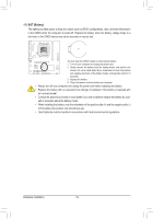
DEBUG PORT 3/4) CPU_FAN/SYS_FAN (Fan Headers) The motherboard has a 4-pin CPU fan header (CPU_FAN) and a 3-pin (SYS_FAN) system fan headers. Most fan headers possess a foolproof insertion design. When connecting a fan cable, be sure to connect it in the correct orientation (the black connector wire is the ground wire). The motherboard supports CPU fan speed control, which requires the use of a CPU fan with fan speed control design. For optimum heat dissipation, it is recommended that a system fan be installed inside the chassis. 1 CPU_FAN 1 SYS_FAN CPU_FAN: Pin No. Definition 1 GND 2 +12V / Speed Control 3 Sense 4 Speed Control SYS_FAN: Pin No. 1 2 3 Definition GND +12V Sense • Be sure to connect fan cables to the fan headers to prevent your CPU and system from overheating. Overheating may result in damage to the CPU or the system may hang. • These fan headers are not configuration jumper blocks. Do not place a jumper cap on the headers. 5) LPT (Parallel Port Header) The LPT header can provide one parallel port via an optional LPT port cable. For purchasing the optional LPT port cable, please contact the local dealer. Pin No. Definition Pin No. Definition 1 STB- 14 GND 26 25 2 AFD3 PD0 15 PD6 16 GND 4 ERR- 17 PD7 5 PD1 18 GND 6 INIT- 19 ACK- 7 PD2 20 GND 8 SLIN- 21 BUSY 2 1 9 PD3 10 GND 22 GND 23 PE 11 PD4 24 No Pin 12 GND 25 SLCT 13 PD5 26 GND Hardware Installation - 14 -
-
 1
1 -
2
-
3
-
4
-
5
-
6
-
7
-
8
-
 9
9 -
 10
10 -
 11
11 -
 12
12 -
 13
13 -
 14
14 -
 15
15 -
 16
16 -
 17
17 -
 18
18 -
 19
19 -
20
-
21
-
22
-
23
-
24
-
25
-
26
-
27
-
28
-
29
-
30
-
31
-
32
-
33
-
34
-
35
-
36
-
37
-
38
-
39
-
40
 |
 |
