Gigabyte GA-MA790FX-UD5P Manual
Gigabyte GA-MA790FX-UD5P Manual
 |
View all Gigabyte GA-MA790FX-UD5P manuals
Add to My Manuals
Save this manual to your list of manuals |
Gigabyte GA-MA790FX-UD5P manual content summary:
- Gigabyte GA-MA790FX-UD5P | Manual - Page 1
GA-MA790FX-UD5P AM2+/AM2 socket motherboard for AMD PhenomTM II X3 processor/AMD PhenomTM II X4 processor/ AMD PhenomTM FX processor/AMD PhenomTM X4 processor/ AMD PhenomTM X3 processor/AMD AthlonTM X2 processor/ AMD AthlonTM processor/AMD SempronTM X2 processor/ AMD SempronTM processor User's - Gigabyte GA-MA790FX-UD5P | Manual - Page 2
Motherboard GA-MA790FX-UD5P Feb. 20, 2009 Motherboard GA-MA790FX-UD5P Feb. 20, 2009 - Gigabyte GA-MA790FX-UD5P | Manual - Page 3
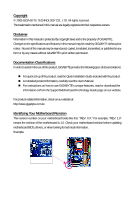
with the product. For detailed product information, carefully read the User's Manual. For instructions on how to use GIGABYTE's unique features, read or download the information on/from the Support\Motherboard\Technology Guide page on our website. For product-related information, check on our - Gigabyte GA-MA790FX-UD5P | Manual - Page 4
Table of Contents Box Contents ...6 OptionalItems...6 GA-MA790FX-UD5P Motherboard Layout 7 Block Diagram...8 Chapter 1 Hardware MB Intelligent Tweaker(M.I.T 41 2-4 Standard CMOS Features 46 2-5 Advanced BIOS Features 48 2-6 IntegratedPeripherals 50 2-7 Power Management Setup 54 2-8 - Gigabyte GA-MA790FX-UD5P | Manual - Page 5
Chipset Drivers 61 3-2 Application Software 62 3-3 Technical Manuals 62 3-4 Contact ...63 3-5 System ...63 3-6 Download Center 64 Chapter 4 Unique Features 65 4-1 Xpress Recovery2 65 4-2 BIOS Update Utilities 68 4-2-1 Updating the BIOS with the Q-Flash Utility 68 4-2-2 Updating the BIOS with - Gigabyte GA-MA790FX-UD5P | Manual - Page 6
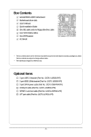
Box Contents GA-MA790FX-UD5P motherboard Motherboard driver disk User's Manual Quick Installation Guide One IDE cable and one floppy disk drive cable Four SATA 3Gb/s cables One SATA bracket I/O Shield • The box contents above are for reference only - Gigabyte GA-MA790FX-UD5P | Manual - Page 7
GA-MA790FX-UD5P Motherboard Layout USB USB 1394_1 1394_2 KB_MS ATX_12V_2X4 CPU_FAN ATX Socket AM2 USB LAN2 PW_SW RST_SW PWR_FAN USB LAN1 AUDIO F_AUDIO RTL 8111DL PCIEX1_1 NB_FAN RTL PCIEX16_1 8111DL PCIEX1_2 CD_IN PCIEX1_3 CODEC SPDIF_IO PCIEX16_2 CI PCI1 IT8720 PCI2 COM AMD - Gigabyte GA-MA790FX-UD5P | Manual - Page 8
/AM2+/AM2 CPU CPU CLK+/-(200 MHz) DDR2 1333(O.C.)/1066/800 MHz DIMM PCIe CLK (100 MHz) PCI Express x16 Hyper Transport 3.0 Dual Channel Memory LAN2 LAN1 3 PCI Express x1 RJ45 RJ45 RTL RTL PCIe CLK 8111DL 8111DL (100 MHz) x1 x1 x1 x1 x1 AMD 790FX PCI Express Bus 2 SATA 3Gb/s x1 GIGABYTE - Gigabyte GA-MA790FX-UD5P | Manual - Page 9
, carefully read the user's manual and follow these procedures: • Prior to installation, do not remove or break motherboard S/N (Serial Number) sticker or you are uncertain about any installation steps or have a problem related to the use of the product, please consult a certified computer technician. - Gigabyte GA-MA790FX-UD5P | Manual - Page 10
PhenomTM X3 processor/AMD AthlonTM X2 processor/ AMD AthlonTM processor/AMD SempronTM X2 processor/ AMD SempronTM processor (Go to GIGABYTE's website for the latest CPU support list.) 5200/2000 MT/s North Bridge: AMD 790FX South Bridge: AMD SB750 4 x 1.8V DDR2 DIMM sockets supporting up to 16 GB of - Gigabyte GA-MA790FX-UD5P | Manual - Page 11
2.0/1.1 ports 2 x RJ-45 ports 6 x audio jacks (Center/Subwoofer Speaker Out/Rear Speaker Out/Side Speaker Out Bridge/Power fan fail warning CPU/System fan speed control (Note 2) BIOS 2 x 8 Mbit flash Use of licensed AWARD BIOS Support for DualBIOSTM PnP 1.0a, DMI 2.0, SM BIOS - Gigabyte GA-MA790FX-UD5P | Manual - Page 12
on the CPU/ system cooler you install. (Note 3) Available functions in EasyTune may differ by motherboard model. (Note 4) Due to the hardware limitation, you must install the AMD AM3 PhenomTM II / AM2+ PhenomTM Series CPU to enable support for Easy Energy Saver. GA-MA790FX-UD5P Motherboard - 12 - - Gigabyte GA-MA790FX-UD5P | Manual - Page 13
CPU: • Make sure that the motherboard supports the CPU. (Go to GIGABYTE's website for the latest CPU support list.) • Always turn off the the CPU socket and the CPU. A Small Triangle Mark Denotes Pin One of the Socket AM2 Socket A Small Triangle Marking Denotes CPU Pin One AM3/AM2+/AM2 CPU - - Gigabyte GA-MA790FX-UD5P | Manual - Page 14
its socket, place one finger down on the middle of the CPU, lowering the locking lever and latching it into the fully locked position. Do not force the CPU into the CPU socket. The CPU cannot fit in if oriented incorrectly. Adjust the CPU orientation if this occurs. GA-MA790FX-UD5P Motherboard - Gigabyte GA-MA790FX-UD5P | Manual - Page 15
the CPU cooler on the CPU. (The following procedure uses the GIGABYTE cooler as the example.) Step 1: Apply an even and thin layer manual for instructions on installing the cooler.) Step 5: Finally, attach the power connector of the CPU cooler to the CPU fan header (CPU_FAN) on the motherboard - Gigabyte GA-MA790FX-UD5P | Manual - Page 16
only one DDR2 memory module is installed. 2. When enabling Dual Channel mode with two or four memory modules, it is recommended that memory of the same capacity, brand, speed, and chips be used and installed in the same colored DDR2 sockets for optimum performance. GA-MA790FX-UD5P Motherboard - 16 - Gigabyte GA-MA790FX-UD5P | Manual - Page 17
compatible to DDR DIMMs. Be sure to install DDR2 DIMMs on this motherboard. Notch DDR2 DIMM A DDR2 memory module has a notch, so it can only fit in one direction. Follow the steps below to correctly install your memory modules in the memory sockets. Step 1: Note the orientation of the memory module - Gigabyte GA-MA790FX-UD5P | Manual - Page 18
expansion card: • Make sure the motherboard supports the expansion card. Carefully read the manual that came with your expansion card. necessary, go to BIOS Setup to make any required BIOS changes for your expansion card(s). 7. Install the driver provided with the GA-MA790FX-UD5P Motherboard - 18 - - Gigabyte GA-MA790FX-UD5P | Manual - Page 19
. B. Supported Operating Systems: Windows Vista and Windows XP. C. BIOS Settings: Driver Setting: After installing the graphics card driver in your operating system, access the Catalyst Control Center. From the CATALYST Control Center, enter the CrossFire menu and select the Enable CrossFire - Gigabyte GA-MA790FX-UD5P | Manual - Page 20
panel with a screw. Step 2: Connect the SATA cable from the bracket to the SATA port on your motherboard. Step 3: Step 4: Connect the power Plug one end of the cable from the bracket SATA signal cable sure to turn off the power of the external enclosure. GA-MA790FX-UD5P Motherboard - 20 - - Gigabyte GA-MA790FX-UD5P | Manual - Page 21
audio out to an external audio system that supports digital optical audio. Before using this feature, ensure that your audio system provides an optical digital audio remove the cable from your device and then remove it from the motherboard. • When removing the cable, pull it straight out from the - Gigabyte GA-MA790FX-UD5P | Manual - Page 22
perform different functions via the audio software. Only microphones still MUST be connected to the default Mic in jack ( ). Refer to the instructions on setting up a 2/4/5.1/ 7.1-channel audio configuration in Chapter 5, "Configuring 2/4/5.1/7.1-Channel Audio." GA-MA790FX-UD5P Motherboard - 22 - - Gigabyte GA-MA790FX-UD5P | Manual - Page 23
1-9 Onboard Switches Quick Switches This motherboard has 3 quick switches: power switch, reset switch and clearing CMOS switch, allowing users to quickly turn on/off or reset the system or clear the - Gigabyte GA-MA790FX-UD5P | Manual - Page 24
devices. • After installing the device and before turning on the computer, make sure the device cable has been securely attached to the connector on the motherboard. GA-MA790FX-UD5P Motherboard - 24 - - Gigabyte GA-MA790FX-UD5P | Manual - Page 25
2x12 Main Power Connector) With the use of the power connector, the power supply can supply enough stable power to all the components on the motherboard. Before connecting the power connector, first make sure the power supply is turned off and all devices are properly installed. The power connector - Gigabyte GA-MA790FX-UD5P | Manual - Page 26
ground wire). The motherboard supports CPU fan speed Bridge and system from overheating. Overheating may result in damage to the CPU/North Bridge or the system may hang. • These fan headers are not configuration jumper blocks. Do not place a jumper cap on the headers. GA-MA790FX-UD5P Motherboard - Gigabyte GA-MA790FX-UD5P | Manual - Page 27
stripe of different color. 34 33 2 1 8) IDE (IDE Connector) The IDE connector supports up to two IDE devices such as hard drives and optical drives. Before attaching the IDE the IDE devices, read the instructions from the device manufacturers.) 40 39 2 1 - 27 - Hardware Installation - Gigabyte GA-MA790FX-UD5P | Manual - Page 28
SATA connector supports a single SATA device. The AMD SB750 controller supports RAID 0, RAID 1, RAID 5, RAID 10 and JBOD. Refer to Chapter 5, "Configuring SATA Hard Drive(s)," for instructions on configuring the total number of hard drives must be an even number. GA-MA790FX-UD5P Motherboard - 28 - - Gigabyte GA-MA790FX-UD5P | Manual - Page 29
and are compatible with SATA 1.5Gb/s standard. Each SATA connector supports a single SATA device. The GIGABYTE SATA2 controller supports RAID 0 and RAID 1. Refer to Chapter 5, "Configuring SATA Hard Drive(s)," for instructions on configuring a RAID array. GSATA2_0 7 1 7 1 GSATA2_1 Pin No - Gigabyte GA-MA790FX-UD5P | Manual - Page 30
12) BATTERY The battery provides power to keep the values (such as BIOS configurations, date, and time information) in the CMOS when the computer is turned off should face up). • Used batteries must be handled in accordance with local environmental regulations. GA-MA790FX-UD5P Motherboard - 30 - - Gigabyte GA-MA790FX-UD5P | Manual - Page 31
a beep code. One single short beep will be heard if no problem is detected at system startup. If a problem is detected, the BIOS may issue beeps in different patterns to indicate the problem. Refer to Chapter 5, "Troubleshooting," for information about beep codes. • HD (Hard Drive Activity LED, Blue - Gigabyte GA-MA790FX-UD5P | Manual - Page 32
panel audio module that has different wire assignments, please contact the chassis manufacturer. 15) CD_IN (CD In Connector, Black) You may connect the audio cable that came with your optical drive to the header. Pin No. Definition 1 CD-L 2 GND 1 3 GND 4 CD-R GA-MA790FX-UD5P Motherboard - Gigabyte GA-MA790FX-UD5P | Manual - Page 33
digital S/PDIF in/out. Via an optional S/PDIF in and out cable, this header can connect to an audio device that supports digital audio out and an audio system that supports digital audio in. For purchasing the optional S/PDIF in and out cable, please contact the local dealer. 1 2 5 6 Pin No - Gigabyte GA-MA790FX-UD5P | Manual - Page 34
16 17 18 19 20 21 22 23 24 25 26 Definition GND PD6 GND PD7 GND ACKGND BUSY GND PE No Pin SLCT GND GA-MA790FX-UD5P Motherboard - 34 - - Gigabyte GA-MA790FX-UD5P | Manual - Page 35
Pin No. 1 2 3 4 5 6 7 8 9 10 Definition NDCD NSIN NSOUT NDTR GND NDSR NRTS NCTS NRI No Pin 21) CI (Chassis Intrusion Header) This motherboard provides a chassis detection feature that detects if the chassis cover has been removed. This function requires a chassis with chassis intrusion detection - Gigabyte GA-MA790FX-UD5P | Manual - Page 36
jumper. Failure to do so may cause damage to the motherboard. • After system restart, go to BIOS Setup to load factory defaults (select Load Optimized Defaults) or manually configure the BIOS settings (refer to Chapter 2, "BIOS Setup," for BIOS configurations). GA-MA790FX-UD5P Motherboard - 36 - - Gigabyte GA-MA790FX-UD5P | Manual - Page 37
latest version of BIOS from the Internet and updates the BIOS. For instructions on using the Q-Flash and @BIOS utilities, refer to Chapter 4, "BIOS Update Utilities." • Because BIOS flashing is potentially risky, if you do not encounter problems using the current version of BIOS, it is recommended - Gigabyte GA-MA790FX-UD5P | Manual - Page 38
boots. A. The LOGO Screen (Default) B. The POST Screen Award Modular BIOS v6.00PG, An Energy Star Ally Copyright (C) 1984-2009, Award Software, Inc. Motherboard Model BIOS Version GA-MA790FX-UD5P E8 . . . . : BIOS Setup : XpressRecovery2 : Boot Menu : Qflash 02/03/2009 - Gigabyte GA-MA790FX-UD5P | Manual - Page 39
& Exit Setup Exit Without Saving ESC: Quit F8: Q-Flash Select Item F10: Save & Exit Setup F11: Save CMOS to BIOS F12: Load CMOS from BIOS Time, Date, Hard Disk Type... BIOS Setup Program Function Keys Move the selection bar to select an item Execute command or enter the submenu - Gigabyte GA-MA790FX-UD5P | Manual - Page 40
integrated audio, BIOS Setup. (Pressing can also carry out this task.) Exit Without Saving Abandon all changes and the previous settings remain in effect. Pressing to the confirmation message will exit BIOS Setup. (Pressing can also carry out this task.) GA-MA790FX-UD5P Motherboard - Gigabyte GA-MA790FX-UD5P | Manual - Page 41
DRAM Configuration ******** System Voltage Optimized System Voltage Control x DDR2 Voltage Control x SB/HT Voltage Control x NB/PCIe/ the overclock/overvoltage settings you made is dependent on your overall system configurations. Incorrectly doing overclock/ supports this feature. - 41 - BIOS Setup - Gigabyte GA-MA790FX-UD5P | Manual - Page 42
you use an AM3 CPU: x4.00 Sets Memory Clock to x4.00. x5.33 Sets Memory Clock to x5.33. x6.66 Sets Memory Clock to x6.66. X8.00 Sets Memory Clock to X8.00. (Note) This item is present only if you install a CPU that supports this feature. GA-MA790FX-UD5P Motherboard - 42 - - Gigabyte GA-MA790FX-UD5P | Manual - Page 43
to those under the same items in the MB Intelligent Tweaker(M.I.T.). DDRII Timing Items Manual allows all DDR2 Timing items below to be configurable. Options are: Auto (default), Manual. (Note) This item is present only if you install a CPU that supports this feature. - 43 - BIOS Setup - Gigabyte GA-MA790FX-UD5P | Manual - Page 44
all voltage control items below to be configurable. (Default: Auto) DDR2 Voltage Control Allows you to set memory voltage. Normal Supplies the memory voltage as required. (Default) +0.1V ~ +0.7V Increases memory voltage by 0.1V to 0.7V at 0.1V increment. GA-MA790FX-UD5P Motherboard - 44 - - Gigabyte GA-MA790FX-UD5P | Manual - Page 45
0.1V to 0.3V at 0.1V increment. NB/PCIe/PLL Voltage Control Allows you to set the North Bridge PCIe PLL voltage. Normal +0.1V ~ +0.3V Supplies the PCIe PLL voltage as required. (Default) Increases Note) This item is present only if you install a CPU that supports this feature. - 45 - BIOS Setup - Gigabyte GA-MA790FX-UD5P | Manual - Page 46
] [None] [None] [None] [None] Drive A Floppy 3 Mode Support [1.44M, 3.5"] [Disabled] Halt On [All, But Keyboard] Base Memory Extended by using one of the two methods below: • Auto Lets BIOS automatically detect IDE/SATA devices during the POST. (Default) • GA-MA790FX-UD5P Motherboard - 46 - - Gigabyte GA-MA790FX-UD5P | Manual - Page 47
to enter the parameters manually, refer to the information ", 720K/3.5", 1.44M/3.5", 2.88M/3.5". Floppy 3 Mode Support Allows you to specify whether the installed floppy disk drive for an error during the POST. All Errors Whenever the BIOS detects a non-fatal error the system boot will stop. - Gigabyte GA-MA790FX-UD5P | Manual - Page 48
AMD K8 Cool&Quiet control Auto Lets the AMD Cool'n'Quiet driver BIOS Main Menu. Setup A password is only required for entering the BIOS Setup program. (Default) System A password is required for booting the system and for entering the BIOS Setup program. GA-MA790FX-UD5P Motherboard - Gigabyte GA-MA790FX-UD5P | Manual - Page 49
appears off (Default: Disabled) Full Screen LOGO Show Allows you to determine whether to display the GIGABYTE Logo at system startup. Disabled displays normal POST message. (Default: Enabled) Init Display First graphics card on the PCIEX16_2 slot as the first display. - 49 - BIOS Setup - Gigabyte GA-MA790FX-UD5P | Manual - Page 50
: Enabled) OnChip SATA Type (AMD SB750 South Bridge, SATA2_0~SATA2_3 connectors) Configures the GIGABYTE SATA 2 chip or configures the SATA controller to AHCI mode. IDE Disables RAID for the SATA controller and configures the SATA controller to PATA mode. (Default) GA-MA790FX-UD5P Motherboard - Gigabyte GA-MA790FX-UD5P | Manual - Page 51
storage driver to enable advanced Serial ATA features such as Native Command Queuing and hot plug. RAID Enables RAID for the SATA controller. Onboard Audio Function Enables or disables the onboard audio the boot ROM integrated with the onboard LAN chip. (Default: Disabled) - 51 - BIOS Setup - Gigabyte GA-MA790FX-UD5P | Manual - Page 52
/1000 Mbps in Windows mode or when the LAN Boot ROM is activated. When a Cable Problem Occurs... If a cable problem occurs on a specified pair of wires, the Status field will show Short and thenlength shown is the approximate length of the attached LAN cable. GA-MA790FX-UD5P Motherboard - 52 - - Gigabyte GA-MA790FX-UD5P | Manual - Page 53
disables the integrated USB 2.0 controller. (Default: Enabled) USB Keyboard Support Allows USB keyboard to be used in MS-DOS. (Default: Enabled) USB Mouse Support Allows USB mouse to be used in MS-DOS. (Default: Disabled is set to ECP or ECP+EPP mode. Options are: 3 (default), 1. - 53 - BIOS Setup - Gigabyte GA-MA790FX-UD5P | Manual - Page 54
Power button USB Wake Up from S3 Modem Ring Resume PME Event Wake Up HPET Support (Note) Power On By Mouse Power On By Keyboard x KB Power ON a modem that supports wake-up function. (Default: Disabled) (Note) Supported on Windows® Vista® operating system only. GA-MA790FX-UD5P Motherboard - 54 - - Gigabyte GA-MA790FX-UD5P | Manual - Page 55
need an ATX power supply providing at least 1A on the +5VSB lead. (Default: Enabled) HPET Support (Note) Enables or disables High Precision Event Timer (HPET) for Windows® Vista® operating system. the settings may not be effective. (Note) Supported on Windows® Vista® operating system only. - 55 - Gigabyte GA-MA790FX-UD5P | Manual - Page 56
DDR2 motherboard CI header. If the system chassis cover is removed, this field will show "Yes", otherwise it will show "No". To clear the chassis intrusion status record, set Reset Case Open Status to Enabled, save the settings to CMOS, and then restart your system. GA-MA790FX-UD5P Motherboard - Gigabyte GA-MA790FX-UD5P | Manual - Page 57
Vcore/DDR2 1.8V Warning Allows the system to emit warning sound if the CPU/system/North Bridge/power fan is not connected or fails. Check the fan condition or CPU Smart FAN Control is set to Enabled. Auto Voltage PWM Lets BIOS autodetect the type of CPU fan installed and sets the optimal CPU fan - Gigabyte GA-MA790FX-UD5P | Manual - Page 58
BIOS Press on this item and then press the key to load the optimal BIOS default settings. The BIOS defaults settings helps the system to operate in optimum state. Always load the Optimized defaults after updating the BIOS or after clearing the CMOS values. GA-MA790FX-UD5P Motherboard - Gigabyte GA-MA790FX-UD5P | Manual - Page 59
changes. When the Password Check item is set to System, you must enter the supervisor password (or user password) at system startup and when entering BIOS Setup. User Password When the Password Check item is set to System, you must enter the supervisor password (or user password) at system startup - Gigabyte GA-MA790FX-UD5P | Manual - Page 60
Abandon all Data F11: Save CMOS to BIOS F12: Load CMOS from BIOS Press on this item and press the key. This exits the BIOS Setup without saving the changes made in BIOS Setup to the CMOS. Press or to return to the BIOS Setup Main Menu. GA-MA790FX-UD5P Motherboard - 60 - - Gigabyte GA-MA790FX-UD5P | Manual - Page 61
other drivers. • After the drivers are installed, follow the onscreen instructions to restart your system. You can install other applications included in the motherboard driver disk. • For USB 2.0 driver support under the Windows XP operating system, please install the Windows XP Service Pack - Gigabyte GA-MA790FX-UD5P | Manual - Page 62
that GIGABYTE develops and some free software. You can click the Install button on the right of an item to install it. 3-3 Technical Manuals This page provides GIGABYTE's application guides, content descriptions for this driver disk, and the motherboard manuals. GA-MA790FX-UD5P Motherboard - 62 - Gigabyte GA-MA790FX-UD5P | Manual - Page 63
3-4 Contact For the detailed contact information of the GIGABYTE Taiwan headquarter or worldwide branch offices, click the URL on this page to link to the GIGABYTE website. 3-5 System This page provides the basic system information. - 63 - Drivers Installation - Gigabyte GA-MA790FX-UD5P | Manual - Page 64
3-6 Download Center To update the BIOS, drivers, or applications, click the Download Center button to link to the GIGABYTE website. The latest version of the BIOS, drivers, or applications will be displayed. GA-MA790FX-UD5P Motherboard - 64 - - Gigabyte GA-MA790FX-UD5P | Manual - Page 65
compress and back up your system data and perform restoration of it. Supporting NTFS, FAT32, and FAT16 file systems, Xpress Recovery2 can back up is recommended to back up your system soon after the operating system and drivers are installed. • The amount of data and hard drive access speed may affect - Gigabyte GA-MA790FX-UD5P | Manual - Page 66
Xpress Recovery2 cannot save the backup file. B. Accessing Xpress Recovery2 1. Boot from the motherboard driver disk to access Xpress Recovery2 for the first time. When you see the following message When finished, go to Disk Management to check disk allocation. GA-MA790FX-UD5P Motherboard - 66 - - Gigabyte GA-MA790FX-UD5P | Manual - Page 67
D. Using the Restore Function in Xpress Recovery2 Select RESTORE to restore the backup to your hard drive in case the system breaks down. The RESTORE option will not be present if no backup is created before. E. Removing the Backup Step 1: If you wish to remove the backup file, select REMOVE. F. - Gigabyte GA-MA790FX-UD5P | Manual - Page 68
. GA-MA790FX-UD5P E8 . . . . : BIOS Setup : XpressRecovery2 : Boot Menu : Qflash 02/03/2009-RD790-SB750-7A66AG06C-00 Because BIOS flashing is potentially risky, please do it with caution. Inadequate BIOS flashing may result in system malfunction. GA-MA790FX-UD5P Motherboard - 68 - Gigabyte GA-MA790FX-UD5P | Manual - Page 69
ESC:Reset :Power Off Total size : 0 Free size : 0 3. Select the BIOS update file and press . Make sure the BIOS update file matches your motherboard model. Step 2: The process of the system reading the BIOS file from the floppy disk is displayed on the screen. When the - Gigabyte GA-MA790FX-UD5P | Manual - Page 70
Setup Load Optimized Defaults F11: Save CMOS to BIOS F12: Load CMOS from BIOS Press to load BIOS defaults Step 6: Select Save & Exit Setup and then press to save settings to CMOS and exit BIOS Setup. The procedure is complete after the system restarts. GA-MA790FX-UD5P Motherboard - 70 - - Gigabyte GA-MA790FX-UD5P | Manual - Page 71
matches your motherboard model. Follow the onscreen instructions to complete. If the BIOS update file for your motherboard is not present on the @BIOS server site, please manually download the BIOS update file from GIGABYTE's website and follow the instruc- tions in "Update the BIOS without Using - Gigabyte GA-MA790FX-UD5P | Manual - Page 72
hardware components such as CPU, chipset, and memory and reduce the useful life of these components. Before you do the overclock/overvoltage, make sure that you fully know each function of EasyTune 6, or system instability or other unexpected results may occur. GA-MA790FX-UD5P Motherboard - 72 - - Gigabyte GA-MA790FX-UD5P | Manual - Page 73
advanced proprietary software design, GIGABYTE Easy Energy Saver is able Interface A. Meter Mode In Meter Mode, GIGABYTE Easy Energy Saver shows how much power Update (Check for the latest utility version) • The above data is for reference only. Actual performance may vary depending on motherboard - Gigabyte GA-MA790FX-UD5P | Manual - Page 74
continue to run in taskbar) 13 INFO/Help 14 Live Utility Update (Check for the latest utility version) C. Stealth Mode In Stealth limitation, you must install the AMD AM3 PhenomTM II / AM2+ PhenomTM Series CPU to enable support for Easy Energy Saver. (Note . GA-MA790FX-UD5P Motherboard - 74 - - Gigabyte GA-MA790FX-UD5P | Manual - Page 75
for using Q-Share After installing Q-Share from the motherboard driver disk, go to Start>All Programs>GIGABYTE> Q-Share.exe to launch the Q-Share tool. shared data folder Changes the data folder to be shared (Note) Updates Q-Share online Displays the current Q-Share version Exits Q-Share (Note - Gigabyte GA-MA790FX-UD5P | Manual - Page 76
the Microsoft Volume Shadow Copy Services technology, Time Repair allows you to quickly back up and restore your system data in the Windows Vista operating system. Time Repair supports NTFS file system and can so you cannot edit the contents of a shadow copy. GA-MA790FX-UD5P Motherboard - 76 - - Gigabyte GA-MA790FX-UD5P | Manual - Page 77
connected network switch or router device supports the IEEE 802.3ad LACP standard. Please refer to your network switch or router device manual for further details. Select Realtek Ethernet Teaming Utility and click Install. Step 1: Insert the motherboard driver disk and select Application Software - Gigabyte GA-MA790FX-UD5P | Manual - Page 78
GA-MA790FX-UD5P Motherboard - 78 - - Gigabyte GA-MA790FX-UD5P | Manual - Page 79
BIOS Setup. C . Configure a RAID array in RAID BIOS. (Note 1) D. Make a floppy disk containing the SATA RAID/AHCI driver for Windows XP. (Note 2) E. Install the SATA RAID/AHCI driver motherboard, the SATA2_0, SATA2_1, SATA2_2, SATA2_3, SATA2_4 and SATA2_5 ports are supported by AMD SB750 South Bridge - Gigabyte GA-MA790FX-UD5P | Manual - Page 80
Step 2: Save changes and exit BIOS Setup. The BIOS Setup menus described in this section may differ from the exact settings for your motherboard. The actual BIOS Setup menu options you will see shall depend on the motherboard you have and the BIOS version. GA-MA790FX-UD5P Motherboard - 80 - - Gigabyte GA-MA790FX-UD5P | Manual - Page 81
to create RAID. Step 1: After the POST memory test begins and before the operating system boot begins, look for a message which says "Press to enter FastBuild (tm) Utility" (Figure 2). Hit the + key to enter the RAID BIOS setup utility. RAID Option ROM Version 3.0.1540.47 (c) 2008 - Gigabyte GA-MA790FX-UD5P | Manual - Page 82
of manually defining the drive elements and RAID levels for one or multiple disk arrays attached to the AMD SB750 Total Drv LD 1 RAID 0 0 Stripe Block: 64 KB Gigabyte Boundary: ON Fast Init: ON Cache Mode: WriteThru [ Drives Page Change Figure 5 GA-MA790FX-UD5P Motherboard - 82 - - Gigabyte GA-MA790FX-UD5P | Manual - Page 83
to return to Main Menu and press again if you want to exit the RAID BIOS utility. View Drive Assignments The View Drive Assignments option in the Main Menu displays whether drives attached to the AMD SB750 controller are assigned to a disk array or are unassigned. Under the Assignment column - Gigabyte GA-MA790FX-UD5P | Manual - Page 84
SATA 3G Capacity (GB) 79.89 80.02 Press Ctrl-Y to delete the data in the disk! or press any other key to abort... Figure 9 GA-MA790FX-UD5P Motherboard - 84 - - Gigabyte GA-MA790FX-UD5P | Manual - Page 85
. On this motherboard, the GSATA2_0 and GSATA2_1 ports are supported by the GIGABYTE SATA2 SATA controller.) Then connect the power connector from your power supply to the hard drive. B. Enabling the SATA controllers and configuring hard drive mode in BIOS Setup Make sure to enable the SATA - Gigabyte GA-MA790FX-UD5P | Manual - Page 86
test begins and before the operating system boot begins, look for a message which says "Press to enter RAID Setup Utility" (Figure 2). Press + to enter the GIGABYTE SATA2 RAID BIOS utility. GIGABYTE information about the selected hard drive. GA-MA790FX-UD5P Motherboard - 86 - - Gigabyte GA-MA790FX-UD5P | Manual - Page 87
key to select RAID 0 (Stripe), RAID 1 (Mirror), or JBOD (Figure 5). Then press to move onto the next step. GIGABYTE Technology Corp. PCIE-to-SATAII/IDE RAID Controller BIOS v1.06.59 [ Create New RAID ] [ Hard Disk Drive List ] Name: GRAID Level: 0-Stripe Disks: Select Disk Block: 128 KB - Gigabyte GA-MA790FX-UD5P | Manual - Page 88
stripe block size (Figure 6), ranging from 4 KB to 128 KB. Press . GIGABYTE Technology Corp. PCIE-to-SATAII/IDE RAID Controller BIOS v1.06.59 [ Create New RAID ] [ Hard Disk Drive List ] Name: GRAID BS]-Delete Number Figure 7 [ENTER]-Next [ESC]-Abort GA-MA790FX-UD5P Motherboard - 88 - - Gigabyte GA-MA790FX-UD5P | Manual - Page 89
array and press . A small window displaying the array information will appear in the center of the screen (Figure 9). GIGABYTE Technology Corp. PCIE-to-SATAII/IDE RAID Controller BIOS v1.06.59 [ Main Menu ] [ Hard Disk Drive List ] Create RAID Disk Drive Delete RAID Disk Drive Revert HDD - Gigabyte GA-MA790FX-UD5P | Manual - Page 90
exiting the RAID BIOS utility, then press (Figure 10). GIGABYTE Technology Corp. PCIE-to-SATAII/IDE RAID Controller BIOS v1.06.78 the SATA RAID/AHCI driver diskette and the installation of the SATA RAID/AHCI driver and operating system. Delete GA-MA790FX-UD5P Motherboard - 90 - [ESC]-Abort - Gigabyte GA-MA790FX-UD5P | Manual - Page 91
refer to the next section, "5-1-4." See the instructions below about how to copy the driver in MS-DOS mode . (Note) Prepare a startup disk that has CD-ROM support and two blank formatted floppy disks. Step 1: Insert the prepared startup disk and motherboard driver disk in your system. Boot from the - Gigabyte GA-MA790FX-UD5P | Manual - Page 92
by an adapter manufacturer. Select the SCSI Adapter you want from the following list, or press ESC to return to the previous screen. AMD AHCI Compatible RAID Controller-x86 platform AMD AHCI Compatible RAID Controller-x64 platform ENTER=Select F3=Exit GA-MA790FX-UD5P Motherboard Figure 2 - 92 - - Gigabyte GA-MA790FX-UD5P | Manual - Page 93
to Figure 3 below will appear. Select (Windows XP/2003) RAID/AHCI Driver for GIGABYTE GBB36X Controller and press . Windows Setup You have chosen to configure a SCSI Adapter for use with Windows, using a device support disk provided by an adapter manufacturer. Select the SCSI Adapter you want - Gigabyte GA-MA790FX-UD5P | Manual - Page 94
assumes that only one RAID array exists in your system.) AMD SB750 SATA controllers: Step 1: Restart your system to boot flash drive containing the driver files and browse to the LH (for Windows Vista 32-bit) or LH64A (for Windows Vista 64-bit) folder. GA-MA790FX-UD5P Motherboard Figure 5 - 94 - Gigabyte GA-MA790FX-UD5P | Manual - Page 95
Step 3: When a screen as shown in Figure 6 appears, select AMD AHCI Compatible RAID Controller and press Next. Figure 6 Step 4: After the driver is loaded, the RAID drive will appear. Select the RAID drive and then press Next to continue the OS installation (Figure 7). Figure 7 The install menus - Gigabyte GA-MA790FX-UD5P | Manual - Page 96
directory: \BootDrv\GSATA\32Bit For Windows Vista 64-bit, browse to the 64Bit folder. Method B: Insert the USB flash drive containing the driver files and browse to \GSATA\32Bit (for Windows Vista 32-bit) or \GSATA\64Bit (for Windows Vista 64-bit). GA-MA790FX-UD5P Motherboard Figure 9 - 96 - - Gigabyte GA-MA790FX-UD5P | Manual - Page 97
Step 3: When a screen as shown in Figure 10 appears, select GIGABYTE GBB36X Controller and press Next. Figure 10 Step 4: After the driver is loaded, select the RAID/AHCI drive(s) where you want to install the operating system and then press Next to continue the OS installation (Figure - Gigabyte GA-MA790FX-UD5P | Manual - Page 98
sure the chipset drivers and ATi SB700/750 RAID Utility have been installed from the motherboard driver disk. Then launch the AMD RAIDXpert from All Programs select Pause/Resume/ Abort/Restart during the rebuilding process. GA-MA790FX-UD5P Motherboard Step 5: When done, the array's status on the - Gigabyte GA-MA790FX-UD5P | Manual - Page 99
rebuilding progress is displayed at the bottom of the screen. When done, the status of the array will display as Normal. GIGABYTE Technology Corp. PCIE-to-SATAII/IDE RAID Controller BIOS v1.06.59 [ Main Menu ] [ Hard Disk Drive List ] Create RAID Disk Drive Delete RAID Disk Drive Revert HDD to - Gigabyte GA-MA790FX-UD5P | Manual - Page 100
the GIGABYTE SATA2 SATA controller driver has been installed from the motherboard driver disk. Launch the GIGABYTE RAID CONFIGURER from All Programs in the Start menu. Step 1: In the GIGABYTE The rebuilding progress is displayed at the bottom of the screen. GA-MA790FX-UD5P Motherboard - 100 - - Gigabyte GA-MA790FX-UD5P | Manual - Page 101
jack and manually configure the jack for microphone functionality. • Audio signals will be present on both of the front and back panel audio connections simultaneously. If you want to mute the back panel audio (only supported when using an HD front panel audio module), refer to instructions on the - Gigabyte GA-MA790FX-UD5P | Manual - Page 102
Audio (For HD Audio Only): Click Device advanced settings on the top right corner on the Speaker Configuration tab to open the Device advanced settings dialog box. Select the Mute the rear output device, when a front headphone plugged in check box. Click OK to complete. GA-MA790FX-UD5P Motherboard - Gigabyte GA-MA790FX-UD5P | Manual - Page 103
allows you to input digital audio signals to the computer for audio processing. S/PDIF In Cable Optical S/PDIF In Coaxial S/PDIF In 1. Installing the S/PDIF In Cable: Step 1: First, attach the connector at the end of the cable to the SPDIF_I header on your motherboard. Step 2: Secure the metal - Gigabyte GA-MA790FX-UD5P | Manual - Page 104
PDIF optical cable (either one) to an external decoder for transmitting the S/PDIF digital audio signals. 2. Configuring S/PDIF Out: On the Digital Output screen, click the Default Format tab and then select the sample rate and bit depth. Click OK to complete. GA-MA790FX-UD5P Motherboard - 104 - - Gigabyte GA-MA790FX-UD5P | Manual - Page 105
With Dolby Home Theater enabled, 2-channel stereo content will be transformed into multi-channel audio, creating a virtual surround sound environment . (Note) Install the Dolby GUI Software driver from the motherboard driver disk. Click the Start icon to All Programs, Dolby Control Center to access - Gigabyte GA-MA790FX-UD5P | Manual - Page 106
Recording Step 1: After installing the audio driver, the HD Audio Manager icon will appear in the notification area. Doubleclick the icon to access the HD Audio Manager. Step 2: Connect your microphone click on Microphone and select Set Default Device. GA-MA790FX-UD5P Motherboard - 106 - - Gigabyte GA-MA790FX-UD5P | Manual - Page 107
, click Start, point to All Programs, point to Accessories, and then click Sound Recorder to begin the sound recording. * Enabling Stereo Mix If the HD Audio Manager does not display the recording device you wish to use, refer to the steps below. The following steps explain how to enable Stereo Mix - Gigabyte GA-MA790FX-UD5P | Manual - Page 108
. 3. To stop recording audio, click the Stop Recording button . Be sure to save the recorded audio file upon completion. B. Playing the Recorded Sound: You can play your recording in a digital media player program that supports your audio file format. GA-MA790FX-UD5P Motherboard - 108 - - Gigabyte GA-MA790FX-UD5P | Manual - Page 109
Troubleshooting 5-3-1 Frequently Asked Questions To read more FAQs for your motherboard, please go to the Support\Motherboard\FAQ page on GIGABYTE's website. Q:In the BIOS Setup program, why are some BIOS options missing? A: Some advanced options are hidden in the BIOS instructions on the motherboard - Gigabyte GA-MA790FX-UD5P | Manual - Page 110
the memory into the memory socket. The problem is verified and solved. Press to enter BIOS Setup. Select "Load Fail-Safe Defaults" (or "Load Optimized Defaults"). Select "Save & Exit Setup" to save changes and exit BIOS Setup. A (Continued...) GA-MA790FX-UD5P Motherboard - 110 - - Gigabyte GA-MA790FX-UD5P | Manual - Page 111
Exit Setup" to save changes and exit BIOS Setup. No The keyboard or mouse might fail. The problem is verified and solved. Turn off the problem, contact the place of purchase or local dealer for help. Or go to the Support\Technical Service Zone page to submit your question. Our customer service - Gigabyte GA-MA790FX-UD5P | Manual - Page 112
product. Restriction of Hazardous Substances (RoHS) Directive Statement GIGABYTE products have not intended to add and safe from office, your household waste disposal service or where you purchased the manual and we will be glad to help you with your effort. GA-MA790FX-UD5P Motherboard - 112 - - Gigabyte GA-MA790FX-UD5P | Manual - Page 113
Finally, we suggest that you practice other environmentally friendly actions by understanding and using the energy-saving features of this product (where applicable), recycling the inner and outer packaging (including shipping containers) this product was delivered in, and by disposing of or - Gigabyte GA-MA790FX-UD5P | Manual - Page 114
GA-MA790FX-UD5P Motherboard - 114 - - Gigabyte GA-MA790FX-UD5P | Manual - Page 115
- 115 - Appendix - Gigabyte GA-MA790FX-UD5P | Manual - Page 116
GA-MA790FX-UD5P Motherboard - 116 - - Gigabyte GA-MA790FX-UD5P | Manual - Page 117
- 117 - Appendix - Gigabyte GA-MA790FX-UD5P | Manual - Page 118
GA-MA790FX-UD5P Motherboard - 118 - - Gigabyte GA-MA790FX-UD5P | Manual - Page 119
231, Taiwan TEL: +886-2-8912-4000 FAX: +886-2-8912-4003 Tech. and Non-Tech. Support (Sales/Marketing) : http://ggts.gigabyte.com.tw WEB address (English): http://www.gigabyte.com.tw WEB address (Chinese): http://www.gigabyte.tw G.B.T. INC. - U.S.A. TEL: +1-626-854-9338 FAX: +1-626-854-9339 Tech - Gigabyte GA-MA790FX-UD5P | Manual - Page 120
in the language list on the top right corner of the website. GIGABYTE Global Service System To submit a technical or non-technical (Sales/ Marketing) question, please link to : http://ggts.gigabyte.com.tw Then select your language to enter the system. GA-MA790FX-UD5P Motherboard - 120 -
-
 1
1 -
 2
2 -
 3
3 -
 4
4 -
 5
5 -
 6
6 -
 7
7 -
8
-
9
-
10
-
11
-
12
-
13
-
14
-
15
-
16
-
17
-
18
-
19
-
20
-
21
-
22
-
23
-
24
-
25
-
26
-
27
-
28
-
29
-
30
-
31
-
32
-
33
-
34
-
35
-
36
-
37
-
38
-
39
-
40
-
41
-
42
-
43
-
44
-
45
-
46
-
47
-
48
-
49
-
50
-
51
-
52
-
53
-
54
-
55
-
56
-
57
-
58
-
59
-
60
-
61
-
62
-
63
-
64
-
65
-
66
-
67
-
68
-
69
-
70
-
71
-
72
-
73
-
74
-
75
-
76
-
77
-
78
-
79
-
80
-
81
-
82
-
83
-
84
-
85
-
86
-
87
-
88
-
89
-
90
-
91
-
92
-
93
-
94
-
95
-
96
-
97
-
98
-
99
-
100
-
101
-
102
-
103
-
104
-
105
-
106
-
107
-
108
-
109
-
110
-
111
-
112
-
113
-
114
-
115
-
116
-
117
-
118
-
119
-
120
 |
 |

GA-MA790FX-UD5P
AM2+/AM2 socket motherboard for
AMD Phenom
TM
II X3 processor/AMD Phenom
TM
II X4 processor/
AMD Phenom
TM
FX processor/AMD Phenom
TM
X4 processor/
AMD Phenom
TM
X3 processor/AMD Athlon
TM
X2 processor/
AMD Athlon
TM
processor/AMD Sempron
TM
X2 processor/
AMD Sempron
TM
processor
User's Manual
Rev. 1001
12ME-MA79F5P-1001R