Haier HC60D1VAR User Manual - Page 10
Vertical Separation between Indoor and Outdoor Units
 |
View all Haier HC60D1VAR manuals
Add to My Manuals
Save this manual to your list of manuals |
Page 10 highlights
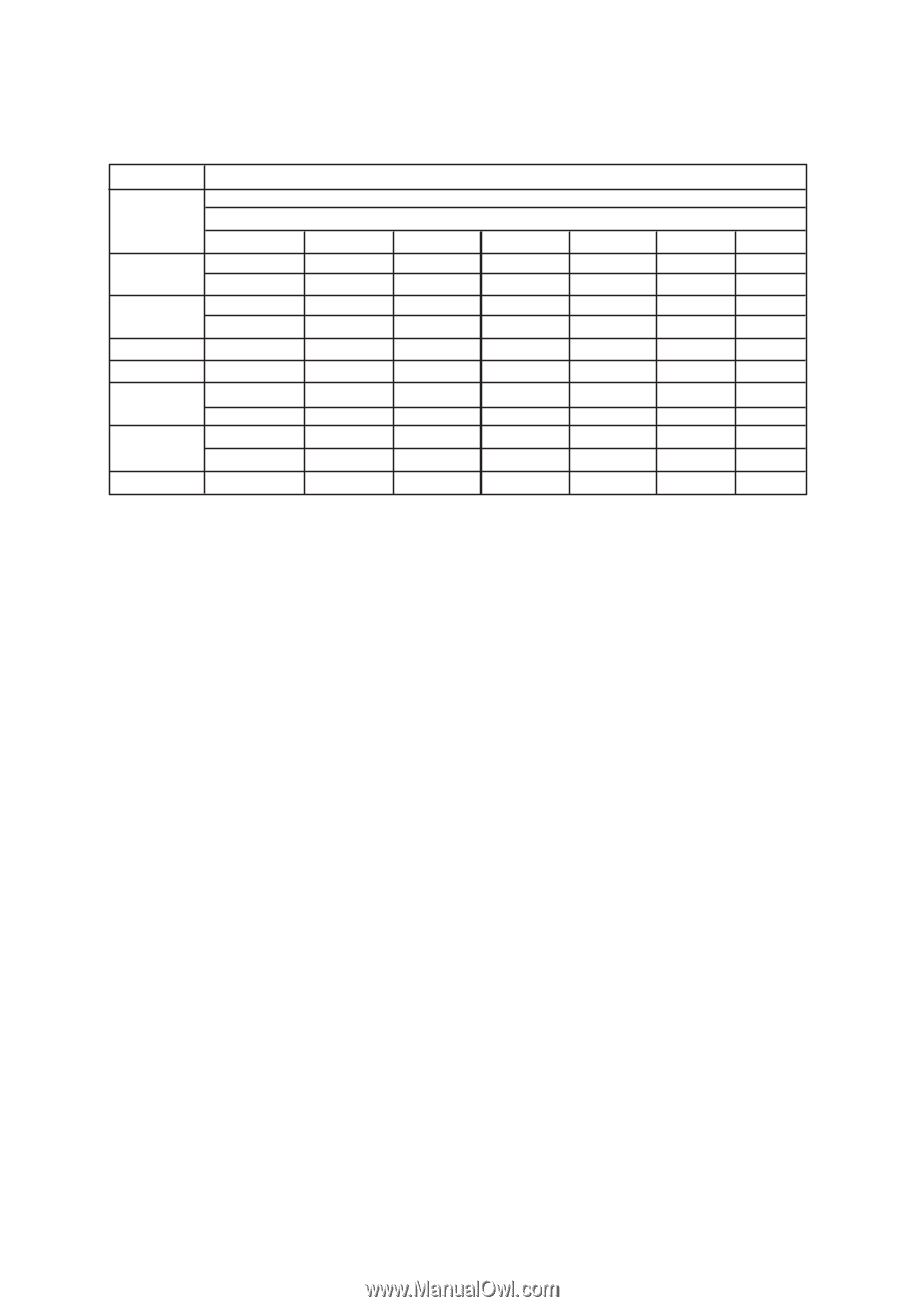
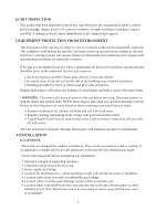
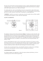
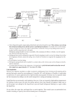
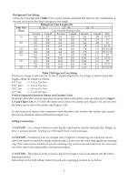
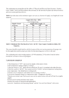
Refrigerant Line Sizing Check the following table (Table 7) for correct suction and liquid line sizes for any combination of the unit size and the maximum refrigerant line length. Refrigerant Line Length (Ft) Unit Size 0 - 24 25 - 49 50 - 74 (Ton) Line Outside Diameter (In) Suction Liquid Suction Liquid Suction Liquid Seer 1.5 5/8 3/8 3/4 3/8 3/4 3/8 10/12 3/4 3/8 3/4 3/8 7/8 1/2 13 2.0 5/8 3/8 3/4 3/8 3/4 3/8 10 3/4 3/8 3/4 3/8 7/8 1/2 12/13 2.5 3/4 3/8 3/4 3/8 7/8 1/2 10/12/13 3.0 3/4 3/8 3/4 3/8 7/8 1/2 10/12/13 3.5 3/4 3/8 7/8 3/8 11/8 1/2 10 7/8 3/8 11/8 3/8 11/8 1/2 12/13 4.0 3/4 3/8 11/8 3/8 11/8 1/2 10 7/8 3/8 11/8 3/8 11/8 1/2 12/13 5.0 7/8 3/8 11/8 3/8 11/8 1/2 10/12/13 Table 7:Refrigerant Line Sizing The factory charge is sufficient for 25 feet of standard liquid line. For longer or shorter liquid line lengths, adjust the charge as follows: 1/4" Line +/- 0.3 oz. Per foot 5/16" Line +/- 0.4 oz. Per foot 3/8" Line +/- 0.6 oz. Per foot 1/2" Line +/- 1.2 oz. Per foot Vertical Separation between Indoor and Outdoor Units Maximum allowable vertical separations between indoor and outdoor units are illustrated in Figure 3-A and Figure 3-B. It's 70' when the indoor unit is below the outdoor unit (Figure 3-A), and 50' when the indoor unit is above the outdoor unit (Figure 3-B). To ensure good oil return to the compressor when the indoor unit is below the outdoor unit, suction line oil trap should be used as illustrated in Figure 3-A. Tubing Connections ! CAUTION - Use extreme caution in removing the caps from the suction and liquid line fittings, as there is pressure present. A fitting is on the liquid line to remove pressure. ! CAUTION - Condensing units are charged with refrigerant. Condensing unit liquid and suction valves are closed to contain the charge within the unit. Do not force the valve stem against the retaining ring. If the valve stem is backed out past the retaining ring, system pressure could force the valve stem out of the valve body and possibly cause personal injury. ! CAUTION - The piston is in the accessory bag. Don't forget to take it out and put into the indoor liquid pipe orifice. Instructions on the field tubing connections and valve opening procedure are as follow: 8
-
 1
1 -
2
-
3
-
4
-
 5
5 -
 6
6 -
 7
7 -
 8
8 -
 9
9 -
 10
10 -
 11
11 -
 12
12 -
 13
13 -
 14
14 -
 15
15 -
16
-
17
 |
 |