Haier HC60D1VAR User Manual - Page 13
System Startup
 |
View all Haier HC60D1VAR manuals
Add to My Manuals
Save this manual to your list of manuals |
Page 13 highlights
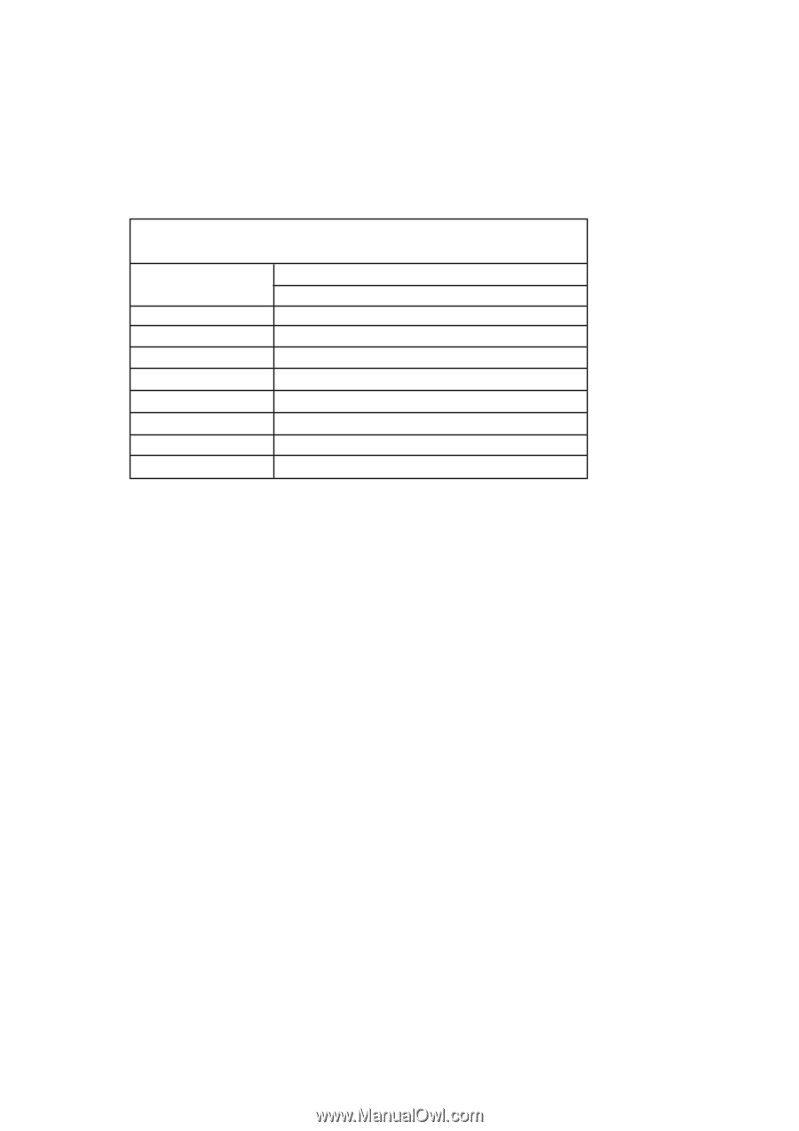
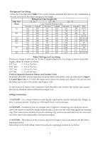
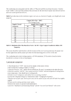
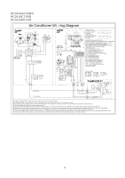
The condensing unit rating plate and the tables of "Physical and Electrical Specifications / Outdoor Units" (Table 1 and 2) provide pertinent data necessary for the selection of proper size electrical service and over-current protection devices. Table 9 provides data on the minimum copper wire size as a function of supply wire length and circuit ampacity. Supply Circuit Ampacity 15 20 25 30 35 40 45 50 Copper Wire Size - AWG (1% Voltage Drop) Supply Wire Length - Ft 50 100 150 200 14 10 8 6 12 8 6 4 10 8 6 4 10 6 4 4 8 6 4 3 8 6 4 2 6 4 3 2 6 4 3 1 Table 9: Minimum Wire Size Based on N.E.C. for 60 C Type Copper Conductors Below 100 Ampacity. The owner should be made familiar with the location of the over-current protection, the proper size for this application and the proper procedure for disconnecting power service to the unit. The condensing unit control wiring requires a 24 Volt minimum, 25 VA service from the indoor transformer as shown on the wiring diagram. 7.SYSTEM STARTUP 1.Turn thermostat to "OFF", turn on power supply at disconnect switch. 2.Turn temperature setting as high as it will go. 3.Turn fan switch to "ON". Indoor blower should run. Be sure it is running in the right direction. 4.Turn fan switch to "AUTO". Turn system switch to "COOL" and turn temperature setting below room temperature. Unit should run in cooling mode. 5.Check to see if compressor and outdoor fan are running correctly? 6.Check the refrigerant charge (see Instructions under "Charging the System"). 7.Replace service port caps. Service port cores are for system access only and will leak if not tightly capped. 8.Check unit for tubing and sheet metal rattles. 9.Instruct the owner on operation and maintenance. Leave this "Installation and Operating Manual" and the "Use and Care Manual" with owner. 11
-
 1
1 -
2
-
3
-
4
-
5
-
6
-
7
-
 8
8 -
 9
9 -
 10
10 -
 11
11 -
 12
12 -
 13
13 -
 14
14 -
 15
15 -
 16
16 -
 17
17
 |
 |