Haier HRF-305 User Manual - Page 20
Dismantling of the upper fixing plate, Connecting the upper fixing plate and refrigerator cabinet
 |
View all Haier HRF-305 manuals
Add to My Manuals
Save this manual to your list of manuals |
Page 20 highlights
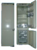
Installation Sequences 4. Dismantling of the upper fixing plate Open the refrigerator door, and draw out upward the O=upper fixing plate cover of S=the upper fixing plate. (2 each in the upper and lower door) _ they are stored separately Loose 2 hex screw fixing O upper fixing plate. (2 each in the upper and lower door) _ they are stored separately Raise and disassemble O upper fixing plate on the refrigerator cabinet door. (2 each in the upper and lower door) _ they are stored separately The upper fixing plate is used when you install refrigerator cabinet door. (for installation method, please refer page 15~17 ) Installation Sequences 5. Connecting the upper fixing plate and refrigerator cabinet door Put the disassembled O upper fixing plate and cabinet door as shown in the diagram, turn the hex screw a little. Draw the cabinet door station meter on the O upper fixing plate to the internal base line of the upper side panel. the internal base line of the upper side panel Upper Fixing PlateO (disassembled status) refrigerator door Upper Fixing Plate O (Assembled status) 36 cabinet door station meter after aligning the height of upper side panel, separate the upper fixing plate and the cabinet. (Refer to page 14) Put the refrigerator cabinet door backside up flatly on a clean floor, and put O= upper fixing plate as shown tightly against the upper end line of furniture. adjust the position, and align the central lines of upper fixing plate and cabinet door, and fix with wood screws. (10 places each) Side panel Cabinet door Position station meter backside of refrigerator cabinet door backside of refrigerator cabinet door Refrigerator cabinet door (Upper) Refrigerator cabinet door (Lower) central line =Draw out the station meter from the upper fixing plate. 37 central line
-
 1
1 -
2
-
3
-
4
-
5
-
6
-
7
-
8
-
9
-
10
-
11
-
12
-
13
-
14
-
 15
15 -
 16
16 -
 17
17 -
 18
18 -
 19
19 -
 20
20 -
 21
21 -
 22
22 -
 23
23
 |
 |
