Haier HRF-305 User Manual - Page 22
wind-up work, A Assembly Method, B Assembly Method, C Assembly Method, D
 |
View all Haier HRF-305 manuals
Add to My Manuals
Save this manual to your list of manuals |
Page 22 highlights
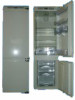
Installation Sequences 8. wind-up work Insert S upper fixing plate cover into upper fixing plate. (2 places, refer to Figure A on Page 19) Insert NM= upper fixing cover into upper/lower (left/ right) sides. (4 places, refer to Figure B on Page 19) Fix R= upper gasket sheet with NQ wood screw, and insert NO bolt cover. put 2 Q side gaskets into the left and right clearance between the refrigerator and the cabinet, and stick them well. (Refer to Figure D on Page 19: Stick the magnetic part of gasket to the side panel of refrigerator.) When change the hinge position, remember to insert U hinge hole sheet. (6 places, refer to Figure E on Page 20) Insert T hinge cover. (4 places, refer to Figure F on Page 20) Install ventilation grill at the mop plate section of the refrigerator cabinet. (It is provided separately) (Refer to Figure G on Page 20) Fix the ventilation grill on the plug-in in the mop plate. Draw back the cover and fix the unfixed right side section of the refrigerator foot. (Refer to Figure H on Page 20) Use NR hinge fixing screw to fix the hinge fixing hole. (refer to Figure I on Page 20) Connect the power cord and confirm that it can function well. (Figure C) (Figure D) (Figure E) (Figure F) (Figure A) (Figure B) (Figure I) (Figure G) 40 (Figure H) Installation Sequences Figure A Assembly Method door Upper door door Lower door Figure B Assembly Method door Upper door door Lower door Figure C Assembly Method door Upper door door Lower door Figure D Assembly Method Refrigerator Cabinet Refrigerator door Refrigerator Cabinet door 41
-
 1
1 -
2
-
3
-
4
-
5
-
6
-
7
-
8
-
9
-
10
-
11
-
12
-
13
-
14
-
15
-
16
-
 17
17 -
 18
18 -
 19
19 -
 20
20 -
 21
21 -
 22
22 -
 23
23
 |
 |
