Haier L32B1120 Product Manual - Page 7
Front panel, Side panel - remote control
 |
UPC - 688057326863
View all Haier L32B1120 manuals
Add to My Manuals
Save this manual to your list of manuals |
Page 7 highlights
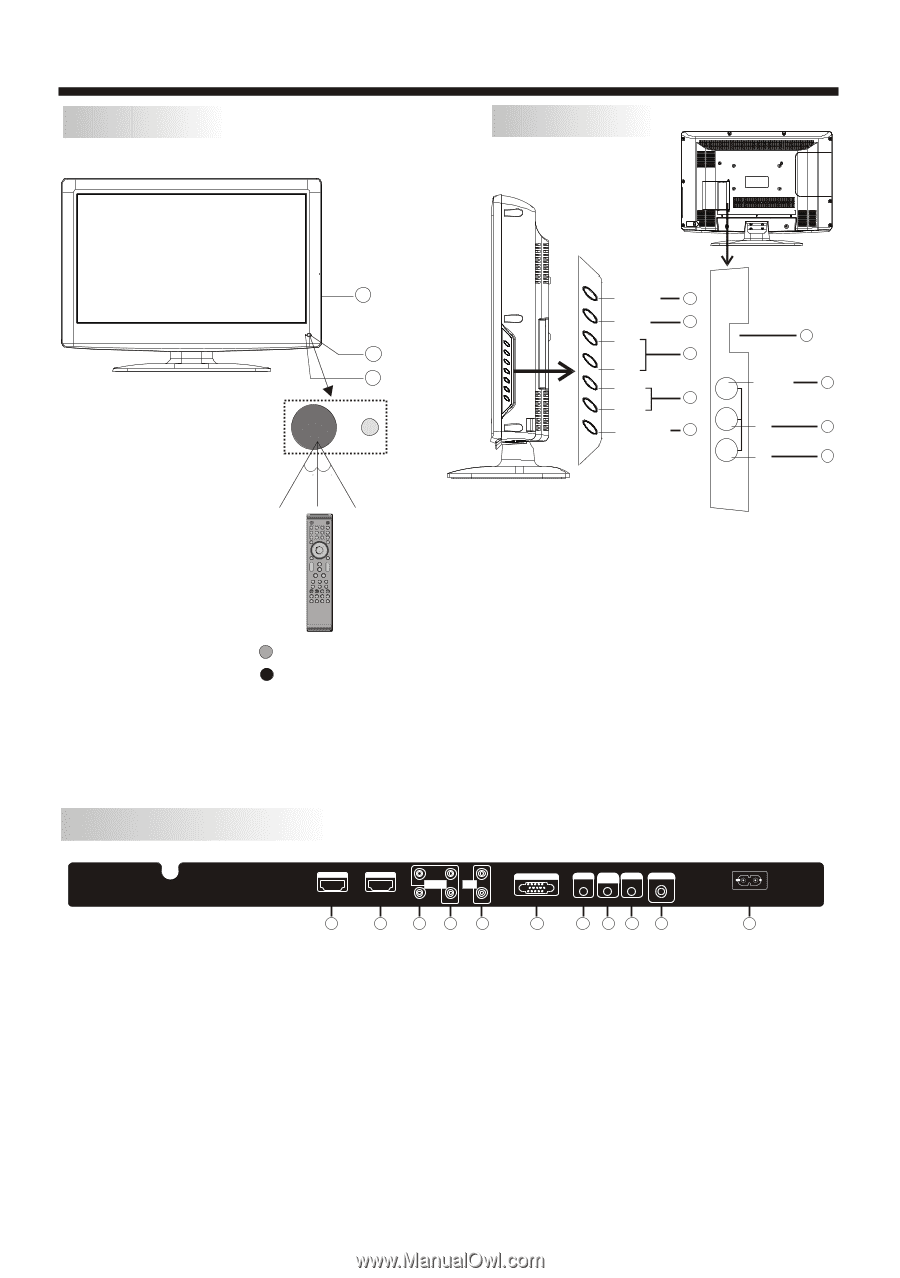
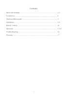
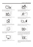
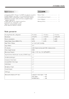
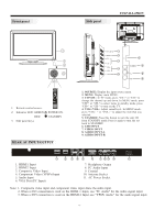
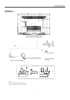
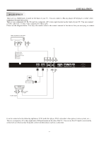
Front panel Side panel INSTALLATION 3 1 2 30 30 SOURCE 1 MENU 2 CH+ 3 CH- VOL+ 4 VOL- STANDBY 5 USB 6 VIDEO 7 VIDEO AV2 L 8 L R 9 R 1 2 3 4 5 6 7 8 9 0 + + VOL CH _ _ 1: Remote control sensor. 2: Indicator LED: GREEN RED 3: Side panel keys POWER ON. STANDBY. REAR AV INPUT/OUTPUT 1. SOURCE: Display the input source menu. 2. MENU: Display main MENU. 3. CH+/CH-: In TV mode, press "CH+" or "CH-" to change the channel up and down. In MENU mode, press "CH+" or "CH-" to select items in standby mode, press "CH+" or "CH-" to turn on the TV. 4. VOL+/VOL-: Adjust sound level. In MENU mode, press "VOL+ " or "VOL- " to adjust the item that you selected. 5. STANDBY: Press this button to turn the unit ON from STANDBY mode. Press it again to turn the set back to STANDBY. 6. USB INPUT 7. VIDEO INPUT 8. AUDIO INPUT-L 9. AUDIO INPUT-R HDMI 1 1 HDMI 2 2 Pr COMPONENT Pb INPUT AUDIO L INPUT AV1 Y R 345 VGA INPUT HEADPHONE PC AUDIO COAXIAL INPUT RF INPUT 6 7 8 9 10 1. HDMI1 Input 2. HDMI2 Input 3. Composite Video Input 4. Component Video (YPbPr) Input 5. Audio Input 6. VGA Port (PC Input) 7. Headphone Output 8. PC Audio Input 9. Coaxial 10. Antenna Socket 11. AC Power Socket AC INPUT 100-240V~50/60Hz 11 Note: 1. Composite video input and component video input share the audio input. 2. When a DVI connection is used on the HDMI 1 Input, use "PC Audio" for the audio signal input. 3. When a DVI connection is used on the HDMI 2 Input, use "YPbPr Audio" for the audio signal input. -6-
-
 1
1 -
 2
2 -
 3
3 -
 4
4 -
 5
5 -
 6
6 -
 7
7 -
 8
8 -
 9
9 -
 10
10 -
 11
11 -
 12
12 -
13
-
14
-
15
-
16
-
17
-
18
-
19
 |
 |