Harman Kardon A250 Owners Manual - Page 4
Dee®, eeeeyke
 |
View all Harman Kardon A250 manuals
Add to My Manuals
Save this manual to your list of manuals |
Page 4 highlights
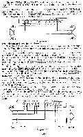
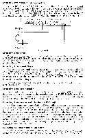
The two SPEAKER SELECTOR switches located on the front panel are inoperative for this method of connection, and their setting is therefore not critical. IMPORTANT: For all methods of stereo operation, the SEPARATE-PARALLEL switch mounted on the front chassis support apron directly behind the pilot light must remain in the "SEPARATE" position. The cage (if used) must be removed to provide access to this switch. RIGHT SPEAKERS 0_0(Dee® LEFT SPEAKERS 16/1 SPEAKER A B 4 8 16 32 B 4 16 2 16.11 SPEAKER IG RIGHT SPEAKER LEFT SPEAKER Diagram A Two Independent Stereo Speaker Systems: The Model A-250 stereo amplifier incorporates a unique switching arrangement enabling the user to operate two independent stereo speaker systems lo- cated in different rooms. Remove the shorting bar between A and B terminals on both SPEAKER out- put strips. Connect a lead from the left speaker in System A to the 16 ohm terminal on the LEFT SPEAKER OUTPUT strip and another lead from this speaker to the A terminal on the same strip. Connect the right speaker in System A to terminals 16 and A on the RIGHT SPEAKER OUTPUT strip. This completes Sys- tem A installation. To install System B connect a lead from the left speaker to the 16 ohm terminal on the LEFT SPEAKER OUTPUT strip and another lead to the B term- inal on the same strip. Now connect the right speaker in System B to the 16 and B terminals on the RIGHT SPEAKER OUTPUT strip. This completes System B installation. (See Diagram B) The above illustration is for 16 ohm speakers. If you are using 8 ohm speak- ers connect to the 8 ohm terminals on the SPEAKER OUTPUT strip rather than to the 16. If one pair of speakers is 8 ohms and the other pair 16 ohms, then connect appropriately. For this type of installation the SPEAKER SELECTOR switches located on the front panel are operative. See Stereo Operating Instructions. IMPORTANT: The SEPARATE-PARALLEL switch located on the front chassis support apron directly behind the pilot light must remain in the "SEPA- RATE" position. The cage (if used) must be removed to provide access to this switch. RIGHT SPEAKERS ®® 0 LEFT SPEAKERS eeeeyke RIGHT SPEAKER A B 4 8 16 32 A 8 4 8 16 32 RIGHT SPEAKER LEFT SPEAKER SYSTEM A Diagram B -3p SYSTEM B LEFT SPEAKER
-
 1
1 -
 2
2 -
 3
3 -
 4
4 -
 5
5 -
 6
6 -
 7
7 -
 8
8 -
 9
9 -
 10
10 -
11
-
12
-
13
-
14
-
15
-
16
 |
 |
