Harman Kardon A250 Owners Manual - Page 5
ADDITIONAL, INFORMATION, Speaker, Phasing, Monaural, Record, USING, MODEL, A-250, MONAURAL,
 |
View all Harman Kardon A250 manuals
Add to My Manuals
Save this manual to your list of manuals |
Page 5 highlights
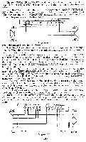
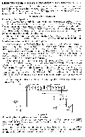
Since several different recording curves have been used in the past (differing with respect to the turnover points and the degree of emphasis or de-emphasis) a choice of playback curves is provided in Harman-Kardon instruments. For all stereophonic records set the EQUALIZATION switch in the RIAA position. For stereophonic tapes set the control to the appropriate tape playback speed. This automatically compensates for the tape equalization. ADDITIONAL INFORMATION Speaker Phasing: When more than one speaker is used in any music reproducing system they must be connected in such a way as to aid each other, rather than to work against each other. Since two speakers must be used for stereo reproduction, this caution applies. Checking for phase, and correcting if necessary, is quite simple, and is done at the time of installation of the system. Play a record with readily apparent bass tones. Listen carefully to the strength and clarity of the bass. Now reverse the connections of one of the speakers. If the bass notes are now louder and clearer, the speakers are now correctly phased. If the bass seems weaker, the original connection was correct. How To Play A Monaural LP Record: If you have been playing stereo records, merely remove the stereo record and put on a monaural record. It's as simple as that! All stereo record players and phonographs are completely compatible with monaural LP records. LP's and stereos may be intermixed on any good stereo record changer. USING THE MODEL A-250 AS A MONAURAL AMPLIFIER INSTALLATION PROCEDURE Connecting Your Speakers: The Model A-250 may be used as a 50 watt monaural amplifier merely by throwing the SEPARATE-PARALLEL switch, located on the front chassis support apron directly behind the pilot light, to the "PARALLEL" position and by strapping the speaker output strips together. IMPORTANT: Whenever the SEPARATE-PARALLEL switch is in the "PARALLEL" position, the speaker output terminals must be strapped together, and conversely, whenever the speaker output terminals are strapped together, the SEPARATE-PARALLEL switch must be in the "PARALLEL" position. Connect one speaker lead to either 32 ohm terminal on the SPEAKER OUT- PUT strip and the other lead to either A terminal. Tie the 32 ohm terminals together. If you are using an 8 ohm speaker, tie the two 16 ohm terminals together instead of the 32 ohm terminals as described. The A and B terminals on both output strips have been strapped together at the factory, and should be left that way. The SPEAKER SELECTOR switches located on the front panel may be placed in any position since they are inoperative for this method of operation. (See DIAGRAM C). F RIGHT SPEAKERS OeA LEFT SPEAKERS Oe ® B 4 8 16 32 B 4 8 16 32 SPEAKER Diagram C
-
 1
1 -
 2
2 -
 3
3 -
 4
4 -
 5
5 -
 6
6 -
 7
7 -
 8
8 -
 9
9 -
 10
10 -
 11
11 -
12
-
13
-
14
-
15
-
16
 |
 |
